How to Choosing RF Connectors: 3 Factors You Should Know
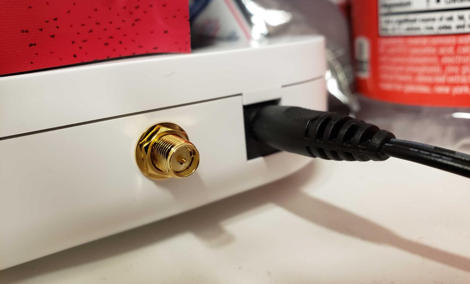
RF connector is a connection device that can reflect and transmit RF signal with a small loss in the RF transmission system and provide fast and repeated connection. Mainly by the contact parts, insulators, shells, and accessories.
RF connector selection conditions should be reliable contact, good conductive insulation performance, sufficient mechanical strength, and plugging and unplugging times to meet the relevant international and domestic standards provisions. At the same time, many factors determine the connector series and style, which is connected to the cable, and the use of frequency range is the main factor.
In engineering practice, make the connector diameter size and cable diameter as similar as possible to minimize reflections. The greater the difference between the cable and connector diameter, the worse the performance. Reflections usually increase as a function of frequency, and generally smaller connectors generally perform well at higher frequency bands. For very high frequencies (above 26 GHz), precision air dielectric connectors are required.
Types of RF Connectors
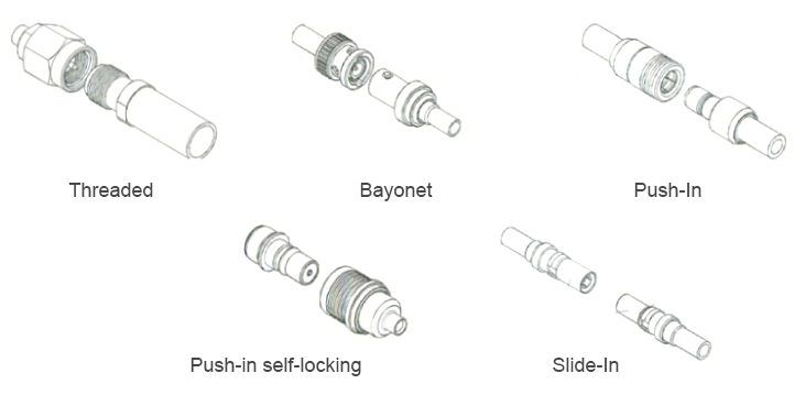

The frequency range determines the family of connectors used. Push-in locking or bayonet snap-lock connectors are typically used at lower frequencies (below 6 GHz). The threaded locking type is usually used in high-performance, low-noise environments.
Threaded connections: Use series such as SMA, TNC, N, UHF and 7/16 for test equipment, military and telecom equipment.
Bayonet: Uses series such as BNC, and MHV, used for reliable and fast connection and plugging, and mostly used in test equipment and military equipment.
Push-in: allows very fast engagement and disengagement. The structure is characterized by reliability, commonly used in small connectors, such as MCX and SMB series.
Push-in self-locking: unique self-locking method is very reliable, usually in high-density small connectors, such as 1.0/2.3, 1.6/5.6 series, plugging and unplugging quickly and locking reliably.
Slide-in type: applied in different DIN multi-terminal type connectors, commonly used for connection on PCB.
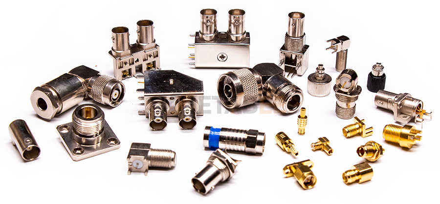

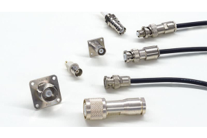
RF Series connectors
Factors to Consider When Selecting RF Connectors
Usually the Cable Specification Determines the Impedance of the Connector
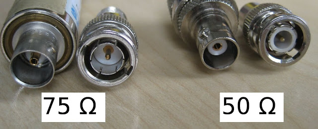
50 and 75 ohms are the two most used standard impedances. Sometimes below 500 MHz, 50 Ohm connectors can be used on 75 Ohm cables (and vice versa) with acceptable performance.
In addition to making the cable and connector match in size as much as possible to minimize errors, the connector interface and insulator material are also important considerations. Interfaces for linear butt and air connections (e.g., SMA and N-type interfaces) provide high-frequency, low-reflection performance while overlapping dielectric interfaces (e.g., BNC and SMB) are typically limited in frequency and reflection performance.
Based on the FCC's (Federal Communications Commission) Chapter 15 extension requirements for non-standard interfaces for radio equipment, many designers choose to have often standard connector interfaces (e.g., BNC, TNC) reverse their polarity, using reverse threaded interfaces.
In some special applications, power and voltage requirements are also a factor in determining connector usage. High power applications require large-diameter connectors (e.g., 7-16 DIN). The transmission power of the cable determines the general transmission power. The peak voltage determines the voltage breakdown rating. Power transfer capability decreases with frequency and altitude.

Voltage Standing Wave Ratio (VSWR) and its Determination
VSWR (Voltage Standing Wave Ratio) measures the signal returned from a connector. Impedance mismatches can cause reflections, and if the cable used is 50 ohms impedance, then the connector must also maintain a 50 ohms impedance. Dimensional changes on the transmission line from the cable to the connector, dielectric crosstalk of the insulator within the connector, and contact loss of the conductor are the main factors leading to a mismatch.
There are two ways to determine the VSWR of the connector. The first method uses the "flat linear limit" method in the entire frequency band. For example, for the mating of flexible cable straight BNC plug, VSWR specified to 4 GHz maximum 1.3:1 (usually written as a maximum of 1.3). The second approach is to consider that VSWR is typically a direct function of frequency in practice, and for straight SMA plugs mated to RG-142 B/U cables, VSWR can be described as VSWR = 1.15 + 0.01*F (GHz) to 12.4GHz max. For example, at 2GHz, the allowable maximum VSWR would be 1.15 + 2*.01 or a maximum of 1.17. At 12.4 GHz, it would be 1.15 + 12.4*.01 or a maximum of 1.274. Naturally, these values can be converted to return loss or reflection coefficient.
In general, within the frequency range of concern, ensure that the VSWR is less than 1.2, but not necessarily to 1.2. Some are in 1.5 or 2 below to meet the requirements. The lower, the better, of course, but the cost will be correspondingly higher.
Insertion Loss and its Determination
Loss is an indicator that all connectors will be concerned about. Usually, RF connector loss will be relatively small (if too large, indicating a problem). Generally, the frequency range of concern is within 0.1 to 0.5 dB.
Insertion loss ρ, defined as
ρ=10*log(Po/Pi), unit dB
Po----Power output
Pi----Power input
Three main causes of insertion loss. Reflection loss, dielectric loss, and conductor loss. Reflection loss refers to those losses that generate connectors because of standing waves. Dielectric loss refers to the loss of energy propagation in the dielectric material (Teflon, rexolite, Delrin, etc.). Conductor loss is caused by energy conduction in the connector conductor surface. It is related to material selection and the use of plating.
Number of Insertion and Extraction
The general RF connector plugging times are 500 or 1000 times. There will be higher requirements.
Summarize
In addition to the above electrical properties of the connector, the mechanical properties of the connector (persistence of the center contact, strength of the connector mechanism as well as vibration, shock, etc.), environmental properties (climate category, sealing, salt spray) and connector durability (mechanical durability, high-temperature durability) are all considerations for choosing the right connector. In practical applications, you can choose your most suitable connector based on the above factors.

