High Voltage Wiring Harness Components - High Voltage Connectors
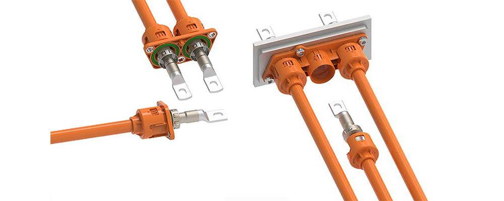
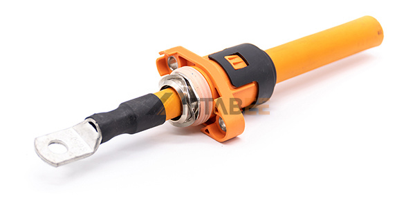
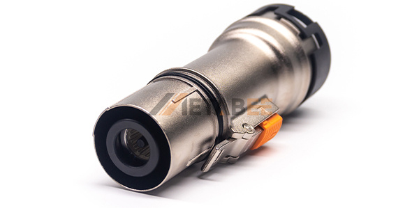
High-voltage connectors, also known as high power connectors, are a type of automotive connectors, generally referred to as connectors with operating voltages above 60V and mainly responsible for transmitting high currents.
High-voltage connectors are mainly used in the electric vehicle high-voltage high-current circuit, and the role of the wire at the same time, the energy of the battery pack through different electrical circuits to the entire vehicle system components, such as battery packs, motor controllers, DCDC converters, chargers and other high-voltage components.
At present, there are three main standard systems for high-voltage connectors, respectively, the LV standard, USCAR standard, and the Japanese standard. These three standards at present to LV standard connectors in the domestic market circulation is the largest, the most complete process standards.

1.High Voltage Connector Basic Structure
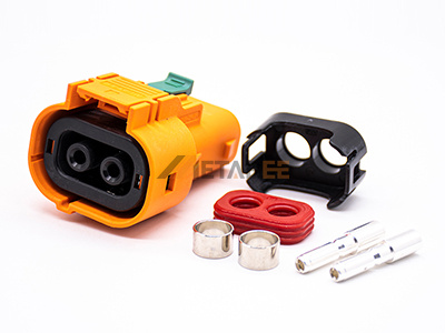
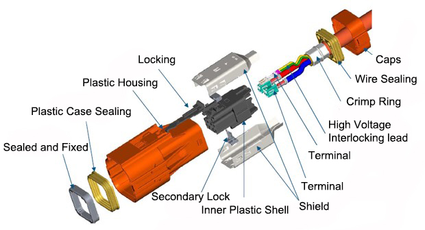
High-voltage connectors are mainly composed of four basic structures, namely contactors, insulators, plastic shells and accessories.
Contactors: the core parts to complete the electrical connection, i.e. male and female terminals, reeds, etc.;
Insulator: support the contact parts and ensure the insulation between the contact parts, i.e. the inner plastic shell;
Plastic shell: the connector shell, to ensure alignment and protection of the entire connector, that is, the outer plastic shell;
Accessories: including structural accessories and installation accessories, i.e. positioning pins, guide pins, connecting rings, sealing rings, turning bars, locking structures, etc.

2. Classification of High-voltage Connectors
High-voltage connectors can be distinguished in a variety of ways. Whether the connector with shielding function, the number of pins connected, etc., can be the definition of the connector classification.
(1) With or without shielding
High-voltage connectors are classified into non-shielded connectors and shielded connectors according to whether they have shielding function or not.
Non-shielded connectors are relatively simple in structure, have no shielding function and are relatively low cost. Used in locations where shielding is not required, such as charging circuits, inside the battery pack and inside the control on appliances covered by metal shells.


Shielded connectors have complex structure, shielding requirements and relatively high cost. Suitable for applications where shielding is required, such as where the exterior of the appliance is connected to a high-voltage harness.


(2) Number of connections
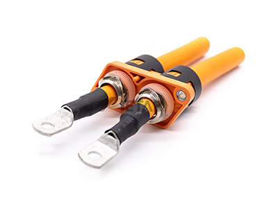
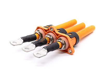
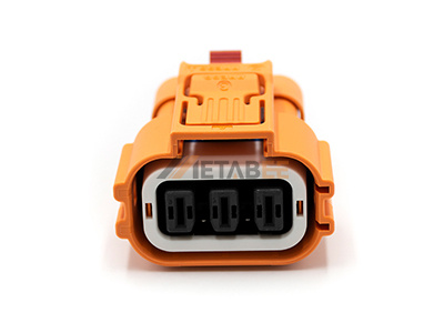
High-voltage connectors are divided into 1P, 2P and 3P connectors according to the number of connection ports (PIN).
1P connector structure is relatively simple, the cost is relatively low. It can meet the requirements of shielding and waterproof of high-voltage system, but the assembly process is slightly complicated and the reworkability is poor. Generally used in battery packs and motors.
2P and 3P connectors have complex structure and relatively high cost. Meet the shielding and waterproof requirements of high-voltage systems, and good maintainability. Generally used for DC input and output, such as on the high-voltage battery pack, controller end, charger DC output end, etc.
3. General Requirements of High-voltage Connectors
High-voltage connectors should follow the requirements specified in SAE J1742, with the following technical requirements:
| Technical Requirements for High Voltage Connectors | |
|---|---|
| Operating Temperature | -40℃-125℃ |
| Withstand Voltage | Meet creepage distance and electrical clearance requirements, meet 750V rated voltage requirements. |
| Insulation Resistance | Under normal conditions, ≥500MΩ |
| Under wet and hot conditions, ≥5MΩ | |
| Contact Resistance | ≤0.2MΩ |
| Insertion and Extraction Times |
≥500 times |
| Seal Protection Grade |
In addition to copper connectors, connectors in the bonding state,regardless of where the connector is installed, the protection level of the connector should not be less than IP68 |
| Protection Grade Against Electric Shock |
IPXXD |
| High Voltage Interlock | To be determined by product type and customer requirements. |
| EMC | 360° shielding for high-voltage connectors with shielding requirements. EMC must comply with the national standard GB/T 37133, harness assembly shielding efficiency ≥ 75dB |
| Anti-corrosion Requirements |
To prevent corrosion of copper connectors, the surface of copper connectors need to be tinned. And pass the LV214 "Automotive Connector Test Specification" related to salt spray test requirements,the conductivity is 100% after the test. |
| Service Life | Plugging life, all connectors meet the requirements of 50 times plugging and unplugging. The connectors must meet the 15-year service life. Connector in use to meet the lifelong maintenance-free use requirements. |
| Color Design | Plastic high-voltage connectors are designed in orange, the same color as the high-voltage conductor. |
| Meet the working voltage of the vehicle and the power of the controlled electrical components | |
Technical Requirements Specified by SAE J1742
4. Design Elements of High-voltage Connectors
High-voltage system requirements for high-voltage connectors include, but are not limited to: high voltage, high current performance; need to be able to achieve a higher level of protection under various conditions (such as high temperature, vibration, impact, dust and water resistance, etc.); have the ability to install; have good electromagnetic shielding performance; cost should be as low as possible and durable.
According to the characteristics and requirements of the above high-voltage connectors should have, at the beginning of the design of high-voltage connectors, the following design elements need to be taken into account as the main elements for targeted design and test verification.
| Design Elements | Element Content | Performance Requirements | Verification Tests |
|---|---|---|---|
| Design of Contact Parts |
Including terminal and plating materials, terminal size, terminal connection structure, terminal and wire connection structure |
Conductivity of connector pin /reed material |
Temperature rise/ transient high current test |
| Reed flexibility and contact area |
Contact resistance and vibration test |
||
| Terminal crimping process, conductor cross-section |
Pulling force test | ||
| Insulation Structure Design |
Internal plastic structure, terminal lock, shield structure, shield flange |
Insulation material flame retardant performance, temperature and voltage resistance level |
Flame retardant / temperature change / corrosion / salt spray test |
| Anti-signal interference | Shielding performance test | ||
| Plastic Shell and Accessories Design |
Wire sealing ring, plastic case sealing ring, plastic case locking structure, wire fixing structure |
Anti-contact | Anti-human contact test |
| Sealability | Airtightness test |
Design Elements, Corresponding Performance and Verification Tests for High-voltage Connectors Cross Reference List
5.Failure Analysis of High-voltage Connectors and Corresponding Measures
In order to improve the reliability of the connector design, the failure mode should be analyzed first so that the corresponding preventive design work can be done.
Connectors usually have poor contact, poor insulation and fixed off three main failure modes.
(1) For poor contact, can be used to detect static contact resistance, dynamic contact resistance, single-hole separation force, connection points and components of vibration resistance and other indicators to be judged;
(2)For poor insulation, can detect the insulator insulation resistance, insulator time degradation rate, insulator, contact parts and other component size indicators to be judged;
(3) For the reliability of the fixed off class, the assembly tolerance of terminals and connectors, torque resistance, connection pin retention force, connection pin insertion force, environmental stress conditions and other indicators can be tested to determine the retention force.
After analyzing the main failure modes and failure forms of connectors, the following measures can be taken to improve the reliability of connector design:
(1) Select the appropriate connector
The choice of connectors should not only consider the type and number of connected circuits, but also facilitate the composition of the device. Such as circular connectors are affected by climate and mechanical factors than rectangular connectors, and mechanical wear and tear is small, and reliable connection with the wire end, so should be as far as possible to choose a circular connector.
(2) Select the appropriate number of contacts
The more the number of contacts in the connector, the lower the reliability of the system, so in the space, weight permitting, try to choose the number of contacts less connectors.
(3) The choice of connectors, should consider the working conditions of the equipment.
This is because the connector's total load current and maximum operating current is often based on the highest temperature conditions in the surrounding environment when working to determine the heat allowed. At the same time in order to reduce the operating temperature of the connector, the connector should be fully considered the heat dissipation conditions, such as the use of the connector from the center of the contact piece to connect the power supply, which is more conducive to heat dissipation.
(4) Waterproof and anti-corrosion.
When the connector works in a corrosive gas, liquid environment, in order to prevent corrosion, attention should be paid to the installation may be installed horizontally from the side after all. When vertical installation is required, liquid should be prevented from flowing down the leads into the connector, and waterproof connectors are generally used.
6.Conclusion
This paper mainly expounds the basic composition, various classifications, design elements, fault analysis and corresponding measures of high-voltage connectors. Through the understanding of these knowledge, we can better select, design, produce and maintain high-voltage connectors, and further ensure the safe and stable operation of high-voltage equipment. Of course, the above are only part of the connector field, and there are still many contents that need to be studied and discussed in depth. If you are interested in our products, please contact us:[email protected]

