RF Coaxial Connectors Guide
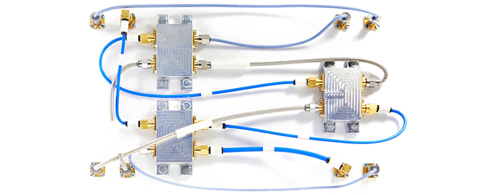
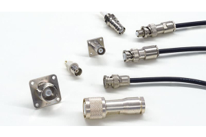
RF coaxial Connectors are electronic parts used to connect RF signals and are commonly used as interfaces in wireless communications or networking equipment. They allow connections between cables, antennas and other RF devices to transmit high frequency signals. RF connectors usually have high performance requirements, such as low insertion loss, high impedance matching, low reflection loss, good shielding, and long-term stability. Common RF coaxial connectors available today include BNC, TNC, SMA, N type, etc.
Types of Common RF Coaxial Connectors
1.BNC
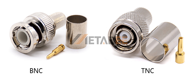
The BNC connector is an RF coaxial connector widely used in the test and measurement field. It is commonly used for low power interconnected RF test equipment (such as audio and signal generators, oscilloscopes and amplifiers). BNC connectors use snap-on retaining rings to provide quick connection and disconnection, and can prevent accidental disconnection. In addition, depending on the application, BNC connectors are typically designed with a characteristic impedance of 50 or 75 ohms. Their frequency range is typically DC - 4 GHz.

2.TNC
The TNC connector is a thread-based BNC connector that provides a safer and more secure connection, avoiding the vibration problems that occur during BNC connector operation. TNC connectors can operate at higher frequencies than BNC connectors, and professional TNC versions are available for high power requirements.
3.SMA
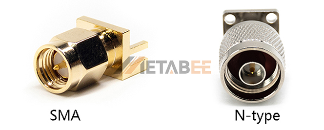
The SMA connector was developed in the 1960s and was very popular for low-power, high-frequency applications. It was originally intended for use in Type 141 semi-rigid coaxial cables and was later extended to flexible cables. The typical size is 5 lb. in. Different versions are available, such as high frequency, self-locking and precision. The SMA is typically used as an interconnect for RF boards, microwave filters and attenuators, and operates at frequencies up to 18 GHz. The precision version extends the upper frequency limit to 26.5 GHz.

4.N-Type
Currently, N-type connectors are an RF coaxial connector widely used in the field of RF. The connector has a rugged construction, long service life and is relatively affordable in terms of price. Standard N-type connectors operate at frequencies up to 11 GHz, while high precision N-type connectors can be increased to 18 GHz. these connectors are commonly used in amplifiers, directional couplers, power meters, coaxial attenuators and other high-precision instrumentation devices, and their connections are highly reliable. In addition, N-type connectors are available in 50 and 75 ohm options, with the 75 ohm version commonly used in the cable television industry.
Selecting the Right Connector
1.Connector Gender
The gender of a RF coaxial connector does not depend exclusively on the gender of the central contact point, but is determined by the configuration of its body. Connectors are divided into male and female plugs, with male plugs having threaded connection nuts or housings and female connectors having external threads. Depending on the central conductor configuration, connectors can be divided into standard polarity (SP) and reverse polarity (RP). Connectors with a male center pin or female center socket are standard polarity, while connectors with a mismatched body and center conductor gender are reverse polarity. Reverse polarity connectors are used for special applications. Care should be taken when using them to avoid damaging the center pin or female center socket.


2.Connector Specifications
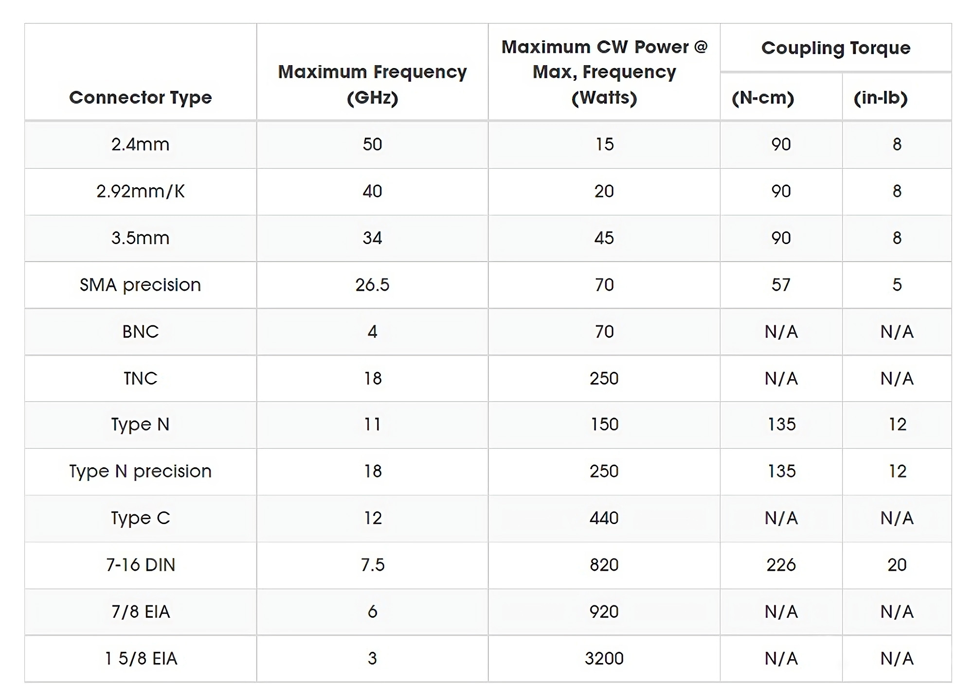
The following table covers the maximum frequency, power and coupling torque parameters of common RF coaxial connectors.

3.Power
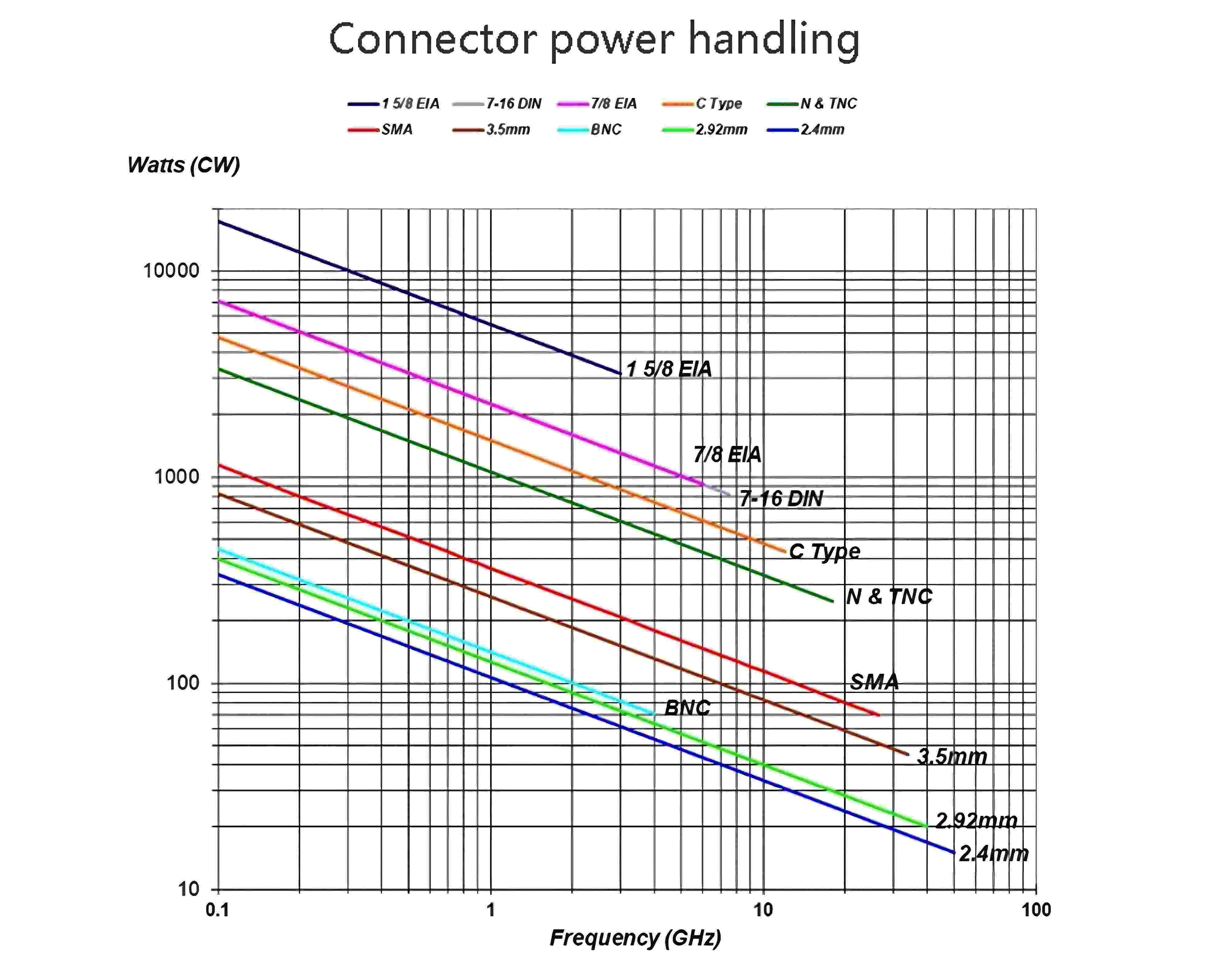
The specific application will determine the frequency range and power handling requirements of the connector. Referring to the table below allows selection of the correct connector type to handle RF coaxial connector types of common construction and materials in a controlled laboratory environment and to meet the conditions of source/load impedance matching. Connector power handling capabilities will vary depending on connector construction, ambient and equipment temperatures, and reflected power. The continuous CW power rating of a connector depends on the temperature rise induced through dissipated power, which is generated by a combination of I2R losses and dielectric losses. Therefore, thermal management becomes a major factor in power ratings.

4.Connector Materials
Materials are one of the determinants of a connector's power handling capability, and dielectric materials have the greatest impact on this. Currently, fluoropolymer materials are widely used to secure and support the center conductor of connectors, with polytetrafluoroethylene (PTFE) being the most common material used. For air dielectric RF coaxial connectors (such as precision 2.4, 2.9 or 3.5mm connectors), they can avoid PTFE altogether and use high temperature resistant materials. For high power connectors, the thermal conductive dielectric then provides better center conductor cooling beyond PTFE.
5.Reflected Power
A mismatched load can cause some of the incident power to be reflected back to the power supply. When these incidents and reflected powers are transmitted on the same cable, standing waves are formed. These standing waves can be quantified by the voltage standing wave ratio (VSWR). VSWRs occur at quarter-wavelength intervals along the cable as current peaks and zeros, with higher currents translating into higher power and more heat generation. The location of the standing wave peak is affected by local heating, resulting in alternating higher and lower temperature regions along the cable. Considering the local heating due to the peak standing wave power, this phenomenon needs to be taken into account.
At lower frequencies, using peak standing wave power is an ideal approach if the wavelength is long and the current peak is wide and well separated from the adjacent current zero point. However, this approach cannot be applied to high frequency scenarios where smaller connectors are used because the short wavelengths cause localized hot and cold regions to be very close together, thus promoting heat transfer between these regions and thus lowering the peak temperature. As the frequency increases, the heat is distributed evenly, thus reducing the peak temperature and VSWR derating starts to approach the average standing wave power. Therefore, other factors should be considered to evaluate the power rating in high frequency scenarios.
Connector Maintenance
RF coaxial Connectors play a key role in the RF link and can effectively enhance the performance of the system. Considering that these components are mechanical in nature and carry RF signals, they need to be used with special care. A damaged connector may not only cause damage to the connector it is related to, but may also lead to expensive replacement costs. Therefore, we recommend taking precautions and using connectors with care. As one of the system components, degradation or breakage of a connector can directly affect the performance of the entire system. Therefore, proper connector maintenance is essential to ensure smooth system operation. Some measures that can be taken to protect connectors are:
- Inspect and clean the connectors regularly.
- When not in use, install dust caps on connectors and adapters to prevent damage, debris and contamination.
- Avoid contact with the mating surfaces.
- Store the connectors in a clean and dry environment and in a protected manner, not loosely in a container.
- Do not drop the connector as this may cause physical damage, especially with precision air dielectric HF connectors.
Due to the mechanical processes involved in connector use, as well as mating and de-mating cycles, connectors wear out and performance degrades. Following proper care, maintenance, storage and mating techniques will maximize the life cycle.

