
D-Sub connectors, often recognized by their distinctive D-shaped metal shell, have been a staple in electronics for decades. From connecting your old computer monitor to robust industrial machinery, these versatile connectors have played a crucial role in transmitting data, power, and signals reliably. But what exactly is a D-Sub, and why has it remained so prevalent in a world of rapidly evolving technology?
In this comprehensive guide, we'll dive deep into the world of D-Sub connectors. We'll explore their fundamental concepts, delve into their various classifications, dissect their structure and materials, and discuss their critical performance parameters. We'll also highlight major manufacturers, offer guidance on selecting the right D-Sub for your needs, and answer some of the most frequently asked questions.
Introduction to D-Sub Connectors
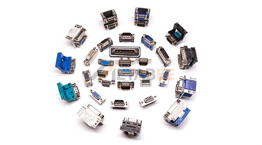
A D-Subminiature connector, commonly known as a D-Sub or DB connector, is a type of electrical connector named for its characteristic D-shaped metal shell. This unique shape serves a crucial purpose: it ensures correct orientation when mating the connector, preventing incorrect insertion and potential damage to pins.
Meaning of D-Subminiature:
- The letter "D" indicates that the connector has a D-shaped metal shell.
- The "subminiature" part of its name referred to its smaller size compared to older connectors when it was first introduced, though by today's standards, some D-Subs might seem quite large!
D-Subs are designed to carry multiple lines of electrical signals or power. They consist of two parts: a male connector (often called a plug) with pins, and a female connector (often called a socket) with corresponding holes. The pins and sockets are arranged in two or more parallel rows within the D-shaped metal shell.
Historically, D-Subs became widely popular with the advent of personal computers, where they were used for serial ports (RS-232), parallel ports, and video output (VGA). Today, their robust design and reliable performance ensure their continued use across a wide range of industrial, medical, and specialized applications.
Relevant Standards
The design and performance of D-Sub connectors are governed by several international standards to ensure interoperability and reliability. The most prominent standards include:
- MIL-DTL-24308 (formerly MIL-C-24308): This is a key military specification that defines the general requirements for D-Subminiature connectors used in military and aerospace applications. It sets stringent standards for performance, materials, and testing.
- IEC 60807 (formerly DIN 41652): An international standard that specifies the dimensions, general requirements, and testing procedures for D-Sub connectors in industrial and commercial applications.
- CECC 75 101-001: European quality assessment system for electronic components.
These standards ensure that D-Sub connectors from different manufacturers can be mated and perform as expected, providing a baseline for quality and reliability.
Key Features
D-Sub connectors boast several key features that contribute to their enduring popularity:
- D-Shaped Shell: This iconic design prevents mis-mating and provides mechanical protection for the contacts. It also offers some degree of EMI/RFI shielding when properly grounded.
- Multi-Contact Arrangement: They can accommodate a large number of pins or sockets in a relatively compact space, making them suitable for applications requiring multiple signal lines.
- Robust Design: The metal shell and sturdy construction make D-Subs highly durable and resistant to physical stress, vibration, and impact.
- Mounting Options: They offer various mounting styles, including cable mount and PCB mount, providing flexibility for different integration needs.
- Locking Mechanisms: Many D-Sub connectors feature jackscrews or slide locks to secure the connection, preventing accidental disengagement due to vibration or tension.
4 Main Types of D-sub Connectors
D-Sub connectors can broadly be categorized into 4 main types based on their density, contact types, and environmental sealing:
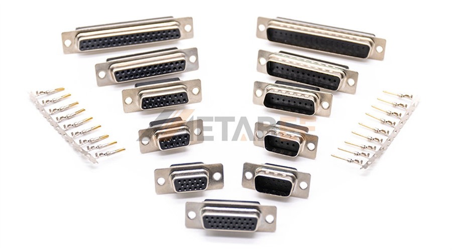
Standard D-Sub Connectors
These connectors are the most common type, featuring contact spacing of approximately 2.77mm (0.1087 inches) between pins. They are widely used for general-purpose signal and data transmission. Examples include the classic DB9 (for serial ports) and DB25 (for parallel ports).
High-Density D-Sub (or HD D-Sub) Connectors
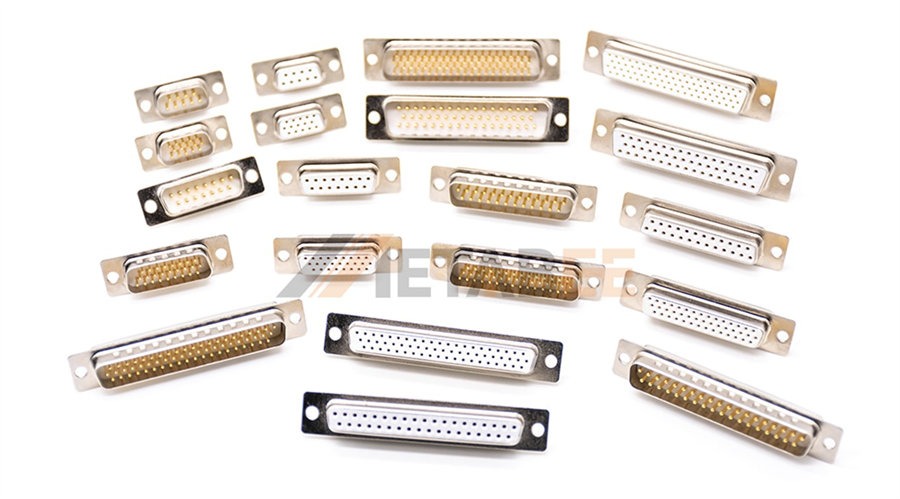
As the name suggests, these connectors pack more contacts into the same shell size as their standard counterparts. They achieve this by arranging contacts in 3 or 4 rows (instead of two for standard D-Subs) and using a smaller contact pitch (around 2.29mm or 0.090 inches). This higher pin count makes them ideal for applications requiring a greater number of signal lines within limited space, such as VGA connectors (which are typically HD15).
Combination D-Sub Connectors
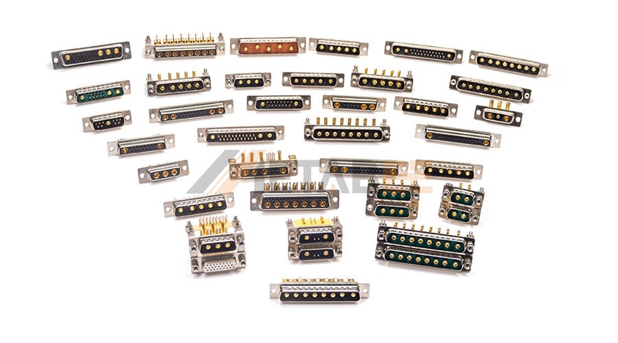
These connectors are incredibly versatile, allowing for a combination of different contact types within a single D-Sub shell. This means you can have standard signal contacts alongside:
- High-Current Contacts: For power delivery.
- Coaxial Contacts: For high-frequency signals (e.g., video, RF).
- High-Voltage Contacts: For specialized power applications.
This hybrid design streamlines cabling and reduces the overall footprint by integrating multiple functions into one connector.
Waterproof D-Sub (or Sealed D-Sub) Connectors
These connectors are designed for harsh environments where exposure to moisture, dust, or other contaminants is a concern. They incorporate specialized sealing mechanisms, such as O-rings or potting compounds, to achieve high IP (Ingress Protection) ratings, IP67 or IP68. They are suitable for outdoor, marine, or industrial applications.
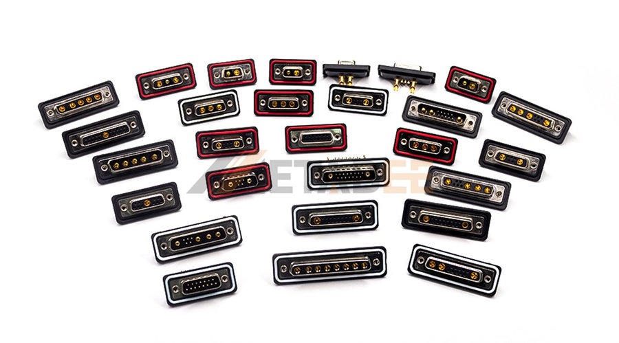
Waterproof IP67 and IP68 D-sub Connectors
Pin Count and Shell Size Relationship Tables
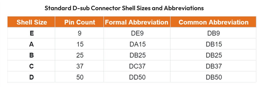
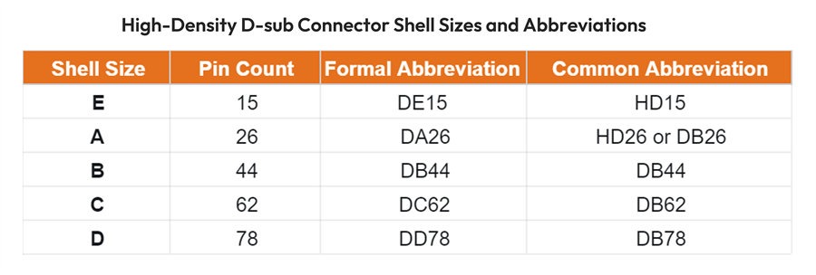
The number of pins (or sockets) in a D-Sub connector is directly related to its shell size. There are five standard shell sizes, typically denoted by letters E, A, B, C, and D.
Standard D-Sub Pin/Shell Relationship:
High-Density D-Sub Pin/Shell Relationship:
D-Sub Formal Abbreviations
This is where things can get a little confusing due to common misnomers. The official military and industry standard notation for D-Sub connectors uses the format DXNN, where:
- D: Denotes the D-Subminiature connector family.
- X: Is a letter indicating the shell size (E, A, B, C, D).
- NN: Represents the actual number of pins/contacts.
So, according to the proper standard, a connector with a "B" shell size and 25 pins should be correctly identified as a DB25. A connector with an "E" shell size and 9 pins is a DE9.
However, in common parlance, especially in the early days of computing, the "B" from DB25 often became generalized to refer to any D-Sub connector. This led to terms like "DB9" becoming widespread, even though technically, a 9-pin D-Sub uses an "E" shell size, making its correct designation DE9. Similarly, the familiar "VGA connector" is typically a 15-pin high-density D-Sub, which should be called a DE15, but is often mistakenly referred to as a DB15 or HD15.
While "DB9" and "DB15" are commonly understood, especially in informal settings, it's good to know the correct, more precise terminology (DE9, DA15, DE15, etc.) for technical specifications and professional contexts.
Structure and Materials of D-Sub Connectors
Understanding the components and materials used in D-Sub connectors helps appreciate their durability and performance.
D-sub Connector Components
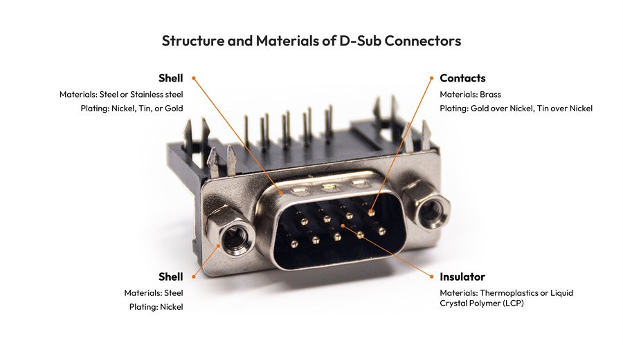
A typical D-Sub connector comprises 4 primary components:
- Shell: This is the D-shaped metal enclosure that gives the connector its distinctive look. It provides mechanical protection for the internal components and, when properly grounded, offers EMI/RFI shielding, preventing external noise from affecting signals and vice-versa.
- Insulator / Dielectric (Insert): Located inside the shell, this is a molded plastic block that holds the contacts in their precise positions and prevents them from short-circuiting. It ensures proper electrical isolation between contacts and the shell.
- Contacts: These are the actual conductive elements that make electrical connection. D-Subs use either pins (male contacts) or sockets (female contacts). Contacts can be designed for various termination methods, including soldering or crimping.
- Mounting Hardware: This includes jackscrews (threaded fasteners) or slide locks. It allows the male and female connectors to be securely fastened together and ensuring a stable connection, especially in environments with vibration.
Materials
The choice of materials significantly impacts the connector's performance, durability, and cost:
Shell Materials and Plating:
The most common materials for D-sub connector shells include steel, zinc alloy, and stainless steel.
- Steel (typically cold-rolled steel): Most common for its strength and cost-effectiveness. Often plated for corrosion resistance and conductivity.
- Zinc Alloy or Stainless Stell: Used for some specialized or higher-end connectors.
Common platings of D-sub connector shells include tin, nickel, or gold for corrosion resistance and improved grounding.
Insulator Materials:
- Thermoplastics (e.g., PBT - Polybutylene Terephthalate, Nylon, PA66): These are common choices due to their excellent electrical insulation properties, dimensional stability, and resistance to heat and chemicals. They are often UL 94V-0 rated, indicating self-extinguishing flame retardancy.
- Liquid Crystal Polymer (LCP): Used for higher performance applications due to its superior mechanical strength, dimensional stability at high temperatures, and chemical resistance.
Contact Materials:
Brass: This is the primary base materials for the pins and sockets, chosen for its good conductivity and mechanical strength (springiness for sockets).
Plating: Contacts are almost always plated to improve conductivity, prevent oxidation, and enhance durability:
- Gold over Nickel: The most common high-performance plating. Gold offers excellent conductivity, corrosion resistance, and wear resistance, while the nickel underplate acts as a barrier to prevent copper migration and provides a hard, durable surface.
- Tin over Nickel: A more cost-effective option, offering good solderability and corrosion resistance, though not as durable or conductive as gold in all conditions.
Key Specifications of D-Sub Connectors
When selecting or specifying a D-Sub connector, several performance parameters are critical to ensure it meets the application's demands.
Dimensions and Shell Sizes
As discussed, the shell size (E, A, B, C, D) dictates the physical footprint of the connector and, consequently, the maximum number of contacts it can house. It's crucial to match the shell size to the available space and the required pin count. High-density versions use the same shell sizes but accommodate more pins by arranging them closer together. Understanding the physical dimensions of each shell size is essential for mechanical design and integration.
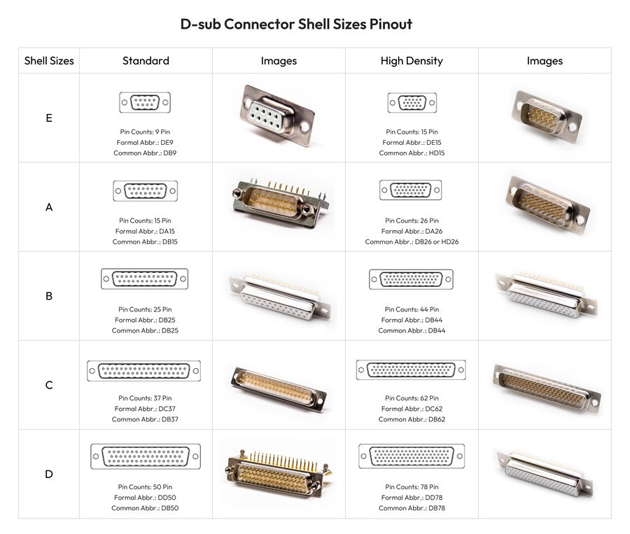
D-sub Connector Shell Sizes and Pinout
Locking Mechanism
A secure connection is paramount, especially in environments prone to vibration or movement. D-Sub connectors offer several locking mechanisms:
- Jackscrews: The most common and robust method. These are threaded screws on the male or female connector that engage with corresponding threaded holes on the mating connector, providing a very secure and reliable connection. They come in various lengths and thread types (e.g., 4-40 UNC).
- Slide Locks / Clip Locks: These mechanisms allow for quicker connection and disconnection compared to jackscrews. They typically involve a spring-loaded clip that snaps into place, offering a moderate level of retention.
- Quick Release Latches: Designed for rapid mating and un-mating, often seen in specific industrial or test applications.
The choice of locking mechanism depends on the application's need for security, frequency of connection/disconnection, and vibration levels.
Rated Current and Voltages
These parameters define the electrical limits of the connector:
Rated Current (Amperage):
This specifies the maximum continuous current that each individual contact can safely carry without exceeding its temperature rise limits. For standard signal contacts, this is typically 2.5A, 5A, or 7.5A per contact. For mixed-layout D-Subs with power contacts, current ratings can be significantly higher, ranging from 10 Amps to 40 Amps per contact. Exceeding the rated current can lead to overheating, material degradation, and connector failure.
Rated Voltage:
This indicates the maximum operating voltage the connector can safely handle between contacts and between contacts and the shell. It includes:
- Working Voltage: The continuous voltage at which the connector is designed to operate. The typical working voltage for standard D-sub connectors is 125V AC/DC.
- Dielectric Withstanding Voltage (DWV) / Hi-Pot Voltage: The maximum voltage the connector can withstand for a short period without breakdown or arcing. This is a test voltage to ensure insulation integrity. The typical dielectric withstanding voltage for standard and high-density D-sub connectors is 1000V AC/DC.
The voltage rating is critical for ensuring electrical safety and preventing arcing or insulation breakdown, especially in high-voltage applications.
IP Rating (Ingress Protection)
For D-Sub connectors used in challenging environments, the IP rating is a vital parameter. The IP code, defined by IEC 60529, indicates the degree of protection provided by electrical enclosures against the intrusion of solids (dust, dirt) and liquids (water).
IP67-rated D-Sub connectors are completely dust-tight and can withstand immersion in water up to 1 meter for 30 minutes. Waterproof D-Subs often incorporate specialized gaskets, O-rings, and sealing compounds to achieve these ratings, making them indispensable for outdoor, marine, or industrial applications where exposure to elements is common.
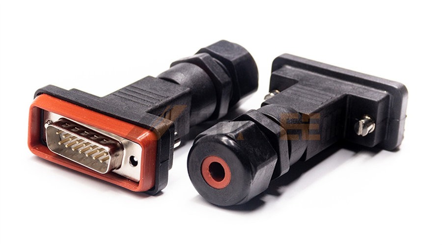
Metabee IP68-rated Waterproof DB15 Connector with plastic shell
Major D-Sub Connector Manufacturers
The D-Sub market is served by a number of reputable manufacturers known for their quality, reliability, and breadth of product offerings. Some of the leading players include:
Conec (part of Amphenol): A key player particularly recognized for its specialized D-Sub products, including filtered D-Subs (for EMI suppression), high-power, and waterproof versions.
NorComp: Specializes primarily in D-Sub connectors, offering a comprehensive portfolio including standard, high-density, waterproof, and mixed-layout options. They are known for their reliable and cost-effective solutions.
TE Connectivity (TE): Another industry giant, TE Connectivity provides robust D-Sub solutions with a focus on high performance and reliability for harsh environments, industrial automation, and data communications.
Molex: While widely known for various connector types, Molex also offers a range of D-Sub connectors for different applications.
Renhotec: It is one of China's leading connector manufacturers, specializing in a wide range of D-sub connectors. Renowned for their competitive pricing and exceptional product quality, the company has established itself as a trusted name in the industry.
These manufacturers continuously innovate, offering new features like higher density, improved shielding, and enhanced environmental sealing to meet evolving industry demands.
How to Choose the Right D-Sub Connector
Selecting the ideal D-Sub connector involves a careful evaluation of your application's specific needs. Here's a structured approach to guide your decision:
1. Application Requirements
- What kind of signals are you transmitting? (e.g., low-speed data, high-speed video, analog, digital, power). This determines the type of contacts needed (signal, coaxial, power).
- Are there current or voltage requirements? Choose contacts and materials rated for the appropriate current and voltage levels.
- Is EMI/RFI shielding critical? Opt for metal shells with proper grounding.
2. Environmental Considerations
- Operating Temperature Range: Ensure the connector materials can withstand the expected temperatures.
- Exposure to Moisture/Dust: If the environment is harsh, choose a waterproof (IP-rated) D-Sub.
- Vibration and Shock: Select connectors with robust construction and secure locking mechanisms (jackscrews are often preferred).
- Chemical Exposure: Verify material compatibility with any chemicals present.
3. Space Constraints and Density
- Available Space: Measure the physical space where the connector will be installed.
- Pin Count Requirement: Determine how many individual connections you need.
- Standard vs. High-Density: If space is limited but many connections are required, a high-density D-Sub may be necessary.
4. Performance Needs
- Mating Cycles: How often will the connector be connected and disconnected? Gold-plated contacts offer better durability for high-mating cycle applications.
- Signal Integrity: For high-speed or sensitive signals, consider shielded cables and connectors, and possibly specialized coaxial contacts in mixed-layout D-Subs.
- Reliability: For mission-critical applications, consider connectors meeting higher standards (e.g., MIL-Spec versions).
5. Mounting Type
- Panel Mount: For mounting to an enclosure panel (e.g., front panel of equipment).
- Cable Mount: For terminating cables (male or female ends).
- PCB Mount: For direct soldering to a printed circuit board (straight or right-angle pins).
- Solder Cup vs. Crimp: Determine your preferred termination method for cable assemblies.
6. Cost Considerations
Balance performance requirements with budget. While higher-spec connectors offer superior performance, they come at a higher cost. Standard D-Subs are generally more economical.
7. Compatibility
If you're replacing an existing connector or integrating into an existing system, ensure the new D-Sub is compatible in terms of shell size, pinout, and mounting.
By systematically addressing these factors, you can confidently choose the D-Sub connector that best suits your application's technical and environmental demands.
Conclusion
The D-Sub connector, with its distinctive D-shaped shell and robust design, has proven to be an incredibly resilient and adaptable interconnect solution. From its humble beginnings in early computing to its current widespread use in industrial automation, medical devices, aerospace, and specialized equipment, the D-Sub's versatility has ensured its continued relevance.
We've explored its fundamental concepts, differentiating between standard, high-density, mixed-layout, and waterproof variations. Understanding the proper shell size designations (DE, DA, DB, DC, DD) and the relationships between shell size and pin count is crucial for accurate specification. We've also delved into the sturdy structure and materials that contribute to their durability, highlighting the importance of shell plating, insulator properties, and contact finishes like gold for optimal performance.
Furthermore, we've examined critical specifications such as current and voltage ratings, robust locking mechanisms like jackscrews, and vital IP ratings for environmental protection. Knowing these specifications is key to ensuring the connector meets the electrical and environmental demands of your application. Finally, recognizing the contributions of major manufacturers and following a structured selection process empowers you to choose the right D-Sub for your specific needs, guaranteeing reliable and long-lasting connections.
While new connector technologies emerge, the D-Sub remains a testament to effective engineering, offering a reliable, cost-effective, and versatile solution for a multitude of interconnection challenges. Its robust nature and ability to transmit diverse signals make it a timeless choice in many industries.
Related Products
- D-sub Connectors
- D-sub Cable Assemblies
- Standard D-sub Connectors
- High-Density D-sub Connectors
- Combo D-sub Connectors

FAQs
1. What is the difference between a male and female D-Sub connector?
A male D-Sub connector (often called a plug) has pins that protrude. A female D-Sub connector (often called a socket or receptacle) has corresponding holes or sockets designed to receive the pins. They are designed to mate together.
2. Can I use a standard D-Sub connector in a high-temperature environment?
Standard D-Sub connectors are typically rated for operating temperatures up to 105°C, depending on the specific materials used (insulator, shell plating). For extremely high-temperature environments, you would need to contact our technical team for specialized D-Subs designed with high-temperature resistant materials.
3. What does "shielded" mean for a D-Sub connector?
A shielded D-Sub connector has a metal shell that, when properly grounded and mated with a shielded cable and connector, helps to block or contain EMI and RFI. This prevents external electrical noise from affecting the signals being transmitted through the connector and also stops noise generated within the system from radiating outwards.
4. Are D-Sub connectors still relevant in modern electronics?
Absolutely! D-sub connectors have been replaced by USB, HDMI, and DisplayPort for many consumer applications. But they remain highly relevant in industrial automation, medical equipment, military and aerospace, test and measurement, and specialized computing. Their robust design, reliable performance, and ability to handle various signal types (including power and coaxial) make them indispensable in these demanding environments.
5. How do I properly crimp or solder D-Sub contacts?
Crimping: Requires a specific crimping tool designed for the contact size. The wire is stripped, inserted into the crimp barrel, and then compressed by the tool, forming a secure mechanical and electrical connection. This method is fast and creates a gas-tight seal.
Soldering: Involves stripping the wire, inserting it into the contact's solder cup, and then applying heat with a soldering iron to melt solder, creating a metallurgical bond between the wire and the contact. This requires skill and proper ventilation. Always use appropriate tools and follow manufacturer guidelines for both methods.
6. What's the purpose of the D-shaped shell?
The D-shaped shell serves two primary purposes:
- Polarization: It ensures that the connector can only be mated in one correct orientation, preventing mis-insertion that could damage pins or cause incorrect electrical connections.
- Shielding: When made of metal and properly grounded, the shell provides a degree of EMI/RFI shielding, protecting the signals inside from external interference and reducing emissions.
7. Can I mix different types of contacts (signal, power) in one D-Sub connector?
Yes, this is the main advantage of combination (or mixed) D-Sub connectors. These connectors are specifically designed to accommodate a combination of standard signal contacts, high-current power contacts, coaxial contacts, or high-voltage contacts within a single D-shaped shell, offering significant space and cable management benefits.
8. What's the typical lifespan of a D-Sub connector?
The lifespan of a D-Sub connector is typically measured in mating cycles. For standard commercial-grade D-Subs, a typical lifespan is around 500 mating cycles.
9. Are all D-Sub connectors compatible with each other (e.g., a DB9 male with any DB9 female)?
Generally, yes, if they are of the same shell size and density type. For example, a standard DE9 male connector (often called DB9) will mate with any standard DE9 female connector. However, a high-density DE15 (HD15) will not mate with a standard DA15 because even though they are both 15-pin, their pin spacing and arrangement are different. Always ensure both sides of the connection are the same type (standard or high-density) and shell size.
10. Where are D-Sub connectors most commonly used today?
Despite advances in connector technology, D-Subs remain prevalent in several key sectors:
- Industrial Automation: For connecting sensors, actuators, PLCs, and human-machine interfaces (HMIs).
- Medical Equipment: In diagnostic devices, patient monitoring systems, and laboratory instruments.
- Aerospace and Defense: Due to their robust and reliable nature, often using MIL-Spec versions.
- Test and Measurement Equipment: For connecting various probes, instruments, and data acquisition systems.
- Legacy IT Systems: Still found on older servers, networking equipment, and specialized industrial computers.
- Custom Electronics: Preferred by engineers for new designs requiring a highly reliable, multi-pin, general-purpose connector.
