
In the vast ecosystem of electromechanical components, few interfaces command the same historical respect and enduring industrial relevance as the D-subminiature connector family. Among these, the DB15 connector stands out as a critical junction point for signal and data transmission across multiple industrial sectors. But what exactly is a DB15 connector, and why does it remain a staple in modern hardware architecture despite the proliferation of high-speed serial buses like USB and Ethernet?
Introduction: What is a DB15 Connector?
Fundamentally, a DB15 connector functions as an electromechanical interface device within the D-subminiature (D-sub) classification. Engineers design these components to facilitate secure, multi-pin connections between wire harnesses and printed circuit boards (PCBs) or discrete cable assemblies. Its distinctive metallic or plastic D-shaped shield ensures correct mechanical orientation during mating. This design effectively prevents reverse-polarity connections, serving as a critical failsafe in complex electronic systems.
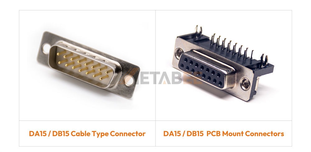
Understanding the D-Subminiature Standard
ITT Cannon originally defined the D-subminiature standard in the 1950s. Today, stringent international and military specifications, most notably MIL-DTL-24308 and DIN 41652, govern these connectors. The "D" in the nomenclature refers to the asymmetric, D-shaped metallic shield surrounding the pin arrays. This shield provides structural rigidity and ensures correct alignment or polarization. It also acts as the primary line of defense against Electromagnetic Interference (EMI) and Radio Frequency Interference (RFI).
Adherence to these standards is non-negotiable in industrial manufacturing. Connectors compliant with MIL-DTL-24308 guarantee a strict baseline of performance. They ensure excellent vibration resistance, thermal shock endurance, and extended mating cycle longevity. The "15" in DB15 denotes the number of conductive pins or sockets housed within the insulator core.
Related Post: What is D-Sub? A Comprehensive Guide to D-Sub Connectors
The Role of DB15 in Electronics
Consumer electronics have largely abandoned D-sub interfaces in favor of highly miniaturized, low-profile alternatives. However, industrial sectors like automation, military hardware, avionics, and medical instrumentation continue to rely heavily on DB15 connectors.
The rationale is straightforward: ruggedness and reliability. Factory environments often experience extreme vibration, high transient voltages, and severe mechanical stress. In these conditions, a locking DB15 connector secured via jack screws will not accidentally decouple. Furthermore, the relatively large contact pitch allows for higher current-carrying capacities and thicker wire gauges (AWG). This advantage makes the DB15 ideal for mixed-signal applications requiring both power and data to traverse a single interface.
If you need reliable components for your mixed-signal applications, contact Metabee today to explore our extensive catalog of DB15 solutions.
Anatomy of a DB15 Connector: Structure and Materials
Understanding the physical construction of a DB15 connector is essential. Engineers rely on specific material choices to ensure durability in harsh environments. Let's break down the core structural components.
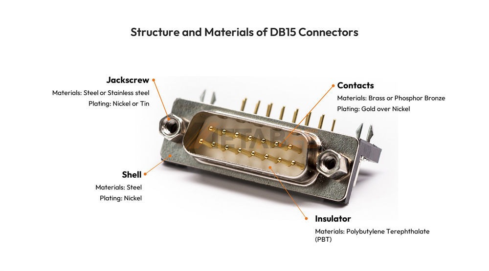
Structure and Materials of DB15 Connectors
The Metal Shell
The iconic D-shaped front shell provides the primary structural framework. Manufacturers typically stamp this shell from steel. They then plate it with tin or nickel. This robust metallic enclosure serves two vital purposes. First, it forces the correct mating orientation. Second, it creates a formidable Faraday cage to block electromagnetic interference (EMI).
The Insulator Core
Inside the metallic shell sits the insulator core. This critical component holds the conductive contacts firmly in place. Manufacturers mold the insulator from high-grade engineering thermoplastics. Polybutylene Terephthalate (PBT) serves as a very common choice. These materials offer excellent dielectric strength. They also easily meet strict UL94V-0 flammability standards.
Conductive Contacts (Pins and Sockets)
The actual pins and sockets handle the electrical transmission. Builders precision-machine or stamp these contacts from copper alloys. They frequently choose brass or phosphor bronze for their excellent spring properties. To guarantee reliable conductivity, manufacturers plate these contacts. The industry standard applies a precise layer of gold over a nickel underplate.
Mounting and Locking Hardware
Industrial environments demand highly secure connections. DB15 connectors utilize robust mounting hardware to prevent accidental disconnections. Engineers frequently specify threaded jackscrews or board locks made of brass or stainless steel. These locking mechanisms easily withstand heavy vibration and mechanical shock.
Standard DB15 (DA-15) vs. High-Density HD15 (VGA or DE15)
Nomenclature surrounding the DB15 creates one of the most pervasive points of confusion in procurement and engineering design. Many people use "DB15" as a colloquial catch-all term. However, this technical inaccuracy can easily lead to costly supply chain errors. It is imperative to distinguish between the Standard Density DA-15 and the High-Density DE-15.
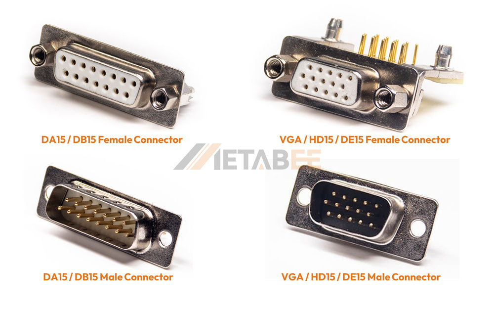
DB15 (DA-15) vs. HD15 (VGA or DE15)
Clearing the VGA Confusion
Under the strict Cannon nomenclature system, the first letter ("D") denotes the series, the second letter denotes the shell size (A, B, C, D, or E), and the number denotes the pin coun
- DA-15 (Standard DB15): This connector utilizes an "A" size shell. It houses 15 pins. This is the true, standard-density 15-pin D-sub connector.
- DE-15 (HD15 / VGA): This connector utilizes a smaller "E" size shell (the same physical shell size as a standard 9-pin DB9). It crams 15 pins into this smaller footprint. This is the high-density 15-pin D-sub connector, globally recognized as the standard VGA (Video Graphics Array) interface.
When ordering a "DB15," buyers must explicitly verify the engineering BOM (Bill of Materials). They need to know if the design requires the larger DA-15 shell or the compact DE-15 shell. Mating a DA-15 plug to a DE-15 receptacle is physically impossible.
Pin Layout Differences (2 Rows vs. 3 Rows)
The architectural differences between the standard and high-density variants dictate their pin arrangements and electrical isolation characteristics:
- Standard DB15 (DA-15) Layout: Features two rows of pins. The top row contains 8 pins, and the bottom row contains 7 pins. The standard pin pitch (distance between pin centers) is 2.77mm (0.109 inches). This wider spacing allows manufacturers to use thicker contact materials and achieve better dielectric withstand voltage. It also accommodates thicker wire gauges, typically up to 20 AWG.
- High-Density DB15 (DE-15/HD15) Layout: Features three rows of 5 pins each. The pin pitch is significantly reduced to 2.29mm (0.090 inches). Because engineers pack the pins much closer together, the current rating per pin is generally lower. Consequently, the acceptable wire gauge is thinner (typically 24-28 AWG).
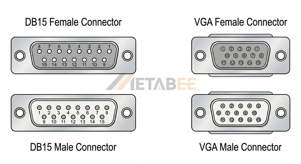
Pin Layout of DA15 and DE15 Connectors
For industrial applications involving power transmission or legacy sensor arrays, engineers prefer the two-row DA-15. Conversely, the three-row DE-15 serves as the standard for purely data-driven, space-constrained video or control signals.
Quick Comparison: DA-15 vs. DE-15
To help simplify the procurement and design process, the following table breaks down the core differences between the standard and high-density DB15 variants:
|
Feature |
Standard DB15 (DA-15) |
High-Density DB15 (DE-15 / HD15) |
|
Shell Size |
A (Larger shell) |
E (Smaller shell, same as DB9) |
|
Total Pins |
15 Pins |
15 Pins |
|
Number of Rows |
2 Rows (8 top, 7 bottom) |
3 Rows (5 pins per row) |
|
Pin Pitch (Spacing) |
2.77mm (0.109 inches) |
2.29mm (0.090 inches) |
|
Typical Wire Gauge |
Up to 20 AWG (Thicker) |
24 to 28 AWG (Thinner) |
|
Current Rating |
3A to 5A per contact |
1A to 3A per contact |
|
Primary Use Cases |
Industrial control, legacy telecom, power/data |
VGA video, high-density data, space-constrained I/O |
|
Mating Compatibility |
Mates ONLY with DA-15 receptacles |
Mates ONLY with DE-15 receptacles |
Core Technical Specifications
Evaluating a DB15 connector for integration into an OEM device requires a deep dive into its electromechanical specifications. Simply specifying the pin count is insufficient for guaranteeing long-term reliability.
Electrical Ratings (Current and Voltage)
The quality of the copper alloy contacts and the insulating properties of the thermoplastic core dictate the electrical thresholds of a DB15 connector.
Current Rating: A standard DA-15 connector typically supports 3 Amps to 5 Amps per contact. Manufacturers usually derate high-density HD15 variants to 1 Amp to 3 Amps. This reduction happens due to the reduced cross-sectional area of the pins and tighter spacing.
Working Voltage: Standard operating voltages generally range from 250V to 300V AC.
Dielectric Withstanding Voltage (DWV): DWV serves as a critical safety metric indicating the maximum voltage the insulation can withstand before breaking down. High-quality DB15 connectors must typically endure 1000V AC (RMS) for 1 minute. They must survive this test without exhibiting electrical arcing or dielectric failure.
Contact Resistance: Connectors must minimize contact resistance to prevent signal degradation and localized heating. Top-tier components guarantee less than 15 milliohms (mΩ) initial resistance and less than 30 mΩ after environmental testing.
Contact Materials and Plating Options
The lifespan of a DB15 connection—measured in mating cycles—is fundamentally tied to its metallurgy.
Base Material: Manufacturers generally stamp and form or screw-machine the contacts from Phosphor Bronze or Brass. Phosphor bronze performs superiorly in female receptacles because it offers excellent spring characteristics and fatigue resistance. This material ensures tight pin retention over thousands of insertions.
Plating: Manufacturers plate the contacts to prevent oxidation and ensure reliable conductivity. The industry standard utilizes Gold over a Nickel underplate.
- Gold Flash: Suitable for static environments with infrequent mating (< 50 cycles).
- 15µ" (microinches) Gold: The standard for industrial applications, providing a balance of cost and durability (~200 mating cycles).
- 30µ" to 50µ" Gold: Engineers reserve this thickness for military, aerospace, and high-reliability applications. These sectors demand extensive mating cycles (500+) and maximum resistance to corrosive environments.
Shielding and EMI/RFI Protection
In industrial facilities saturated with electrical noise from variable frequency drives (VFDs) and heavy machinery, signal integrity is paramount. DB15 connectors offer robust shielding architectures.
Manufacturers typically construct the front shell from steel and plate it with Tin or Nickel. High-quality DB15 plugs incorporate grounding dimples on the male shell for enhanced EMI attenuation. These dimples create multiple points of electrical contact with the female receptacle shell. This design establishes a continuous Faraday cage across the connection, safely routing spurious RF noise to the chassis ground. A DB15 connector provides exceptional EMC (Electromagnetic Compatibility) when paired with shielded cables and metallic backshells.
Metabee engineers specialize in superior shielding designs. Reach out to us today to discuss how we can eliminate EMI issues in your equipment.
Detailed Technical Specifications Summary
For quick reference, here is a comprehensive breakdown of the typical electromechanical parameters for standard industrial DB15 connectors:
|
Parameter Category |
Specification |
Typical Value / Rating |
|
Electrical |
Current Rating |
3A - 5A (Standard DA-15) / 1A - 3A (High-Density DE-15) |
|
|
Voltage Rating |
250V - 300V AC |
|
|
Dielectric Withstanding Voltage |
1000V AC (RMS) for 1 minute |
|
|
Contact Resistance |
≤ 15 mΩ (initial) |
|
|
Insulation Resistance |
≥ 5000 MΩ at 500V DC |
|
Mechanical |
Mating Cycles |
50 (Gold flash) to 500+ (30µ" to 50µ" Gold) |
|
|
Wire Gauge Compatibility |
Up to 20 AWG (DA-15) / 24-28 AWG (DE-15) |
|
Material |
Contact Base Material |
Phosphor Bronze or Brass |
|
|
Contact Plating |
Gold over Nickel Underplate |
|
|
Insulator Material |
Thermoplastic (e.g., PBT), UL94V-0 Rated |
|
|
Shell Material |
Steel (Tin or Nickel plated) |
|
Environmental |
Operating Temperature |
-55°C to +105°C (Standard) / Up to +125°C (High-temp) |
|
|
IP Rating |
IP20 (Standard) / IP67 (Ruggedized variants) |
Primary Applications in Industries
Modern protocols overshadow the DB15 connector in the consumer space. However, this interface thrives in specific industrial verticals where engineers value deterministic performance and mechanical resilience above sheer bandwidth.
Industrial Automation and Motor Control
Factory automation systems frequently deploy standard DB15 (DA-15) connectors. They serve as reliable interfaces for servo motor encoders, stepper motor controllers, and Programmable Logic Controller (PLC) I/O modules. The secure screw-lock mechanisms thrive in high-vibration environments like CNC machining centers or robotic assembly lines. They effectively prevent intermittent signal loss during operation. Additionally, the 15-pin layout provides ample capacity for discrete analog signals, digital I/O, and dedicated power lines within a single harness.
Medical Equipment and Instrumentation
Equipment designers extensively utilize DB15 connectors in diagnostic imaging machines, patient monitoring systems, and analytical laboratory instrumentation. Their robust pin design ensures seamless transmission of critical sensor data like multi-lead ECGs without noise interference. Furthermore, specifying high-mating-cycle gold contacts ensures longevity in demanding clinical settings. Hospital staff can frequently connect and disconnect these cables without degrading performance.
Legacy Telecommunications Networks
The DA-15 connector boasts a rich history in telecommunications and enterprise networking. Engineers most notably used it as the Attachment Unit Interface (AUI) in early thicknet Ethernet networks. While thicknet is now obsolete, countless legacy systems still rely on DB15 interfaces. Facilities use them for PBX telecom switches, diagnostic ports, and alarm monitoring relays. Upgrading these massive systems often proves cost-prohibitive. This reality ensures a continuous aftermarket demand for high-quality DB15 harnesses.

Key Considerations for Engineering and Procurement
Selecting the right DB15 connector involves navigating a complex matrix of termination styles and environmental specifications. Procurement teams and hardware engineers must align on the following parameters. This alignment ensures optimal manufacturability and reliable field performance.
Termination Styles (Solder Cup, PCB Mount, Crimp)
How the connector interfaces with the rest of the system dictates assembly costs and reliability:
- Solder Cup: The classic method for discrete wire assemblies. Technicians manually solder wires into small cups at the rear of the pins. This approach works best for low-volume, high-mix custom wire harnesses or field repairs.
- PCB Mount (Straight or Right Angle): Used for integrating the DB15 directly onto a motherboard or expansion card. Right-angle mounts serve as the standard for rear I/O panels, while straight mounts handle internal headers. Assembly facilities must use precise wave soldering or reflow soldering processes to install them. These processes often strictly comply with IPC-A-610 standards.
- Crimp and Poke: Highly recommended for high-volume harness manufacturing. Automated machinery crimps wires onto individual pins. Assemblers then snap these pins into the connector insulator. This efficient method ensures consistent mechanical strength, reduces labor costs, and eliminates cold solder joints.
- Insulation Displacement Contact (IDC): Used exclusively with flat ribbon cables. Assembly tools press the connector onto the cable. The contacts pierce the insulation and touch the conductors simultaneously. This method enables rapid mass termination, though engineers generally limit it to lower current applications.
Environmental Protection and IP Ratings
Standard DB15 connectors carry an IP20 rating. They offer basic protection against solid objects but provide zero protection against moisture. For deployment in harsh environments, hardware buyers must specify ruggedized variants.
- IP67 Waterproof DB15s: For outdoor telecommunications enclosures or marine electronics, IP67-rated DB15 connectors are mandatory. Manufacturers utilize internal silicone O-rings and specialized potting compounds at the rear wire seals. They also add waterproof mounting gaskets to prevent water and dust ingress, even during temporary submersion.
- Flammability and Compliance: The thermoplastic insulator must meet strict UL94V-0 flammability standards to prevent the spread of fire. Furthermore, global supply chains dictate strict compliance rules. Manufacturers must ensure all connectors adhere to RoHS (Restriction of Hazardous Substances) and REACH directives.
Relate Products
- DB15 Connectors
- VGA/HD15 Connectors
- D-sub Connectors
- Waterproof D-sub Connectors
- Combo D-sub Connectors
Conclusion
The DB15 connector remains an indispensable component in the hardware engineering toolkit. This holds true for both the standard DA-15 two-row configuration and the high-density DE-15 three-row format. Its legacy stems from unyielding reliability, mechanical superiority, and excellent EMI shielding rather than cutting-edge bandwidth.
Engineering and procurement teams must deeply understand the critical nuances of pin layouts, contact plating, and termination styles. This knowledge allows them to select the optimal connector for specific industrial applications and avoid costly field failures. Whether you are designing a next-generation automation controller or sourcing replacement harnesses, component quality matters. As an industry leader, Metabee guarantees premium materials and rigorous testing for every connector.
Are you specifying DB15 connectors for your next industrial project? Contact the Metabee engineering team today to request structural drawings, technical datasheets, or a free product sample tailored to your precise application requirements.
Frequently Asked Questions (FAQs)
Q: What is the main difference between a standard DB15 and an HD15 (VGA) connector?
A: The standard DB15 (DA-15) features two rows of pins housed in a larger "A" size shell. The HD15 (DE-15) features three rows of pins packed tightly into a smaller "E" size shell (the same size as a DB9 connector). The HD15 is typically used for VGA video signals, while the DA-15 is used for industrial control and legacy data.
Q: Can I connect a standard DA-15 plug into an HD15 (DE-15) receptacle?
A: No. Because they utilize completely different shell sizes and have different pin pitches (spacing), mating a standard DA-15 to an HD15 is physically impossible. You must carefully verify the required shell size on your Bill of Materials.
Q: What is the typical current rating for a DB15 connector?
A: A standard two-row DA-15 connector usually supports 3 Amps to 5 Amps per contact. Because of the smaller pin size and tighter spacing, high-density DE-15 connectors are derated and typically support only 1 Amp to 3 Amps per contact.
Q: Are DB15 connectors completely waterproof?
A: By default, standard DB15 connectors carry an IP20 rating, meaning they provide no protection against moisture. However, for outdoor or harsh environments, you can source ruggedized DB15 variants equipped with silicone O-rings and waterproof gaskets that achieve an IP67 rating.
Q: Why are DB15 connectors still used instead of modern USB interfaces?
A: DB15 connectors remain standard in industrial settings because of their mechanical ruggedness. They feature screw-locking hardware that prevents accidental decoupling during extreme vibration. Additionally, they can carry mixed signals (higher power lines and data) simultaneously, which most modern consumer cables cannot easily match.
