
In the rapidly evolving landscape of modern electronics, where devices are becoming smaller, smarter, and more rugged, the weakest link is often the connection itself. For engineers and product designers, ensuring reliable power transmission and data integrity across thousands of connection cycles is paramount. This critical requirement for high performance and exceptional longevity is precisely what drives the demand for Spring-Loaded Connectors, better known by their industry nickname: the Pogo Pin.
What is a Pogo Pin? The Definition
A Pogo Pin is a precision-machined, three-part electromechanical component—comprising a Plunger, Barrel, and Spring—engineered to establish a reliable, temporary, or semi-permanent electrical connection. It is also commonly referred to as a Spring-Loaded Connector (SLC), Spring Loaded Pin, or Spring Probe.
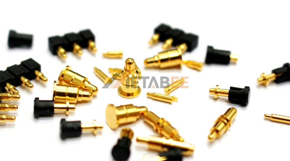
METABEE Pogo Pins and Pogo Pin Connectors
The Pogo Pin's unique structure, defined by its internal spring mechanism, offers a highly specialized and robust solution to the challenge of durable connectivity. This mechanism ensures a consistent and controlled electrical path. Furthermore, it maintains connection integrity even when subjected to shock, vibration, and minor misalignment—situations where conventional connectors often struggle.
The compact and durable design of the Pogo Pin—named for the vertical, jumping motion of its internal mechanism—has consequently made it indispensable across high-reliability industries. Throughout this comprehensive guide, we will dissect the pogo pin’s precise anatomy and explore its crucial working principle, including the critical "wiping action." We will then detail the diverse applications that solidify its role as a cornerstone of modern connectivity solutions.
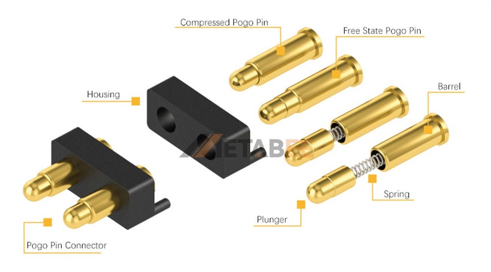
Anatomy of a Pogo Pin: Key Components
The effectiveness of a pogo pin lies in the precise interaction of its 3 primary parts, each manufactured with exacting tolerances and performance-driven materials.
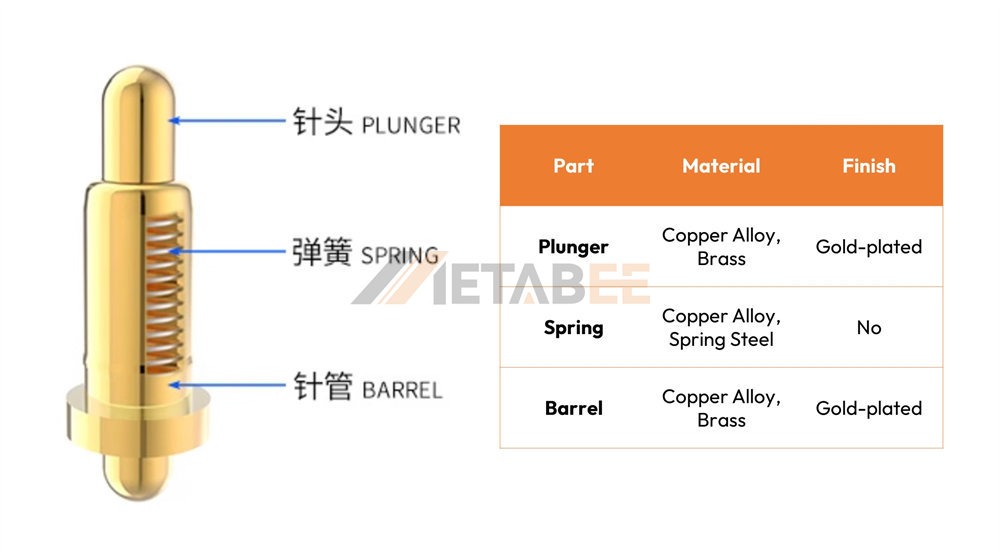
A. The Plunger
The plunger is the dynamic element, serving as the interface that physically contacts the mating surface, typically a PCB pad or a component. Its performance is critically dependent on its construction materials and tip geometry. Plungers are often machined from highly conductive and durable copper alloys such as Beryllium Copper or Brass, which offer excellent spring properties and high electrical conductivity.
Crucially, the plunger’s surface is almost universally plated with Gold. This gold plating (typically hard gold over a nickel barrier) is vital because it prevents oxidation, which would otherwise rapidly increase contact resistance. Secondly, it provides an exceptionally durable surface capable of withstanding tens of thousands of mating cycles without significant wear.
The terminal end comes in various head styles, each optimized for different mating surfaces:
- Pointed or Sharp: For penetrating contaminants or oxides on hard-to-clean surfaces, commonly used in test probes.
- Round/Spherical: The most common style, offering self-centering capability and tolerance for slight angular misalignment.
- Concave/Cup: Ideal for mating with spherical or dome-shaped contacts, offering a highly stable connection for high-vibration environments.
- Flat: Used for mating with flat pads, providing a large contact area when alignment is guaranteed.
B. The Barrel
The barrel acts as the rigid external housing and internal guide for the plunger and spring assembly. Manufactured from materials like brass, the barrel’s internal diameter and straightness are critical for maintaining low contact resistance and ensuring smooth, reliable movement of the plunger.
The importance of tight tolerances here cannot be overstated. A barrel machined to incorrect specifications can lead to plunger binding (sticking), excessive friction, or instability, all of which compromise the pin's lifespan and electrical reliability. The external dimensions are designed for easy integration, whether through press-fit installation or soldering to a PCB board.
C. The Spring
The spring is the core of the pogo pin mechanism. Its sole function is to apply a constant, controlled compression force, known as the spring force, to the plunger tip. This force is essential for overcoming any contaminants, ensuring physical contact, and maintaining that contact when subjected to external forces like shock or vibration.
Common spring materials include Copper Alloy or Spring Steel. The spring force is a critical specification, measured in grams (g) or ounces (oz). It is carefully selected based on the application’s requirements for durability and the fragility of the mating surface. A spring that is too weak may lose contact; one that is too strong may damage the target pad.
D. Plating Material
As mentioned, the standard plating for the plunger and the inner barrel surface is Gold, which is applied over a crucial Nickel underplate. This choice is non-negotiable for high-reliability applications. The underlying nickel layer significantly enhances the mechanical durability and structural integrity of the plating. The outer gold layer offers exceptional chemical stability, preventing the formation of resistive oxide layers. This combination is crucial for achieving the consistently low contact resistance necessary for high-speed data transmission and high-efficiency power transfer.
How Pogo Pins Work (Working Principle)
The pogo pin’s genius lies in its dynamic contact method, which actively works to improve connection quality every time it is used.
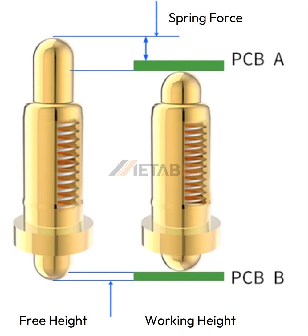
The Connection Cycle and Wiping Action
When the pogo pin is compressed against a target pad, the process involves 3 critical stages:
- Initial Contact: The plunger tip touches the mating surface.
- Compression and Force Application: As the device is mated, the plunger retracts into the barrel, compressing the spring and storing potential energy. This stored energy is converted into a constant normal force pressing the tip onto the pad.
- The "Wiping Action": This is the key differentiator. As the plunger is slightly pressed, the precise machining of the tip and barrel causes the plunger to slightly shift laterally (or "wipe") across the mating surface before it settles into its final position. This critical scraping motion cleans away microscopic contaminants, dust, oils, and non-conductive oxide films that would otherwise impede the electrical flow. This mechanical cleaning ensures that the electrical connection is made against pure, clean metal, guaranteeing ultra-low and highly stable contact resistance.
Importance of Stroke
Engineers must specify the correct stroke for their application. The working stroke is the ideal compression distance where the pin achieves its optimal performance (reliable contact force and lowest resistance). The maximum stroke is the absolute limit the pin can be safely compressed before internal damage or binding occurs. Over-compression beyond the working stroke often leads to rapid fatigue, reduced spring life, and premature failure, severely impacting the pin's guaranteed cycle lifespan.
Electrical Characteristics: Resistance and Impedance
Pogo pins are engineered for minimal electrical degradation. Their tightly controlled structure and gold-on-gold contact ensures very low contact resistance, typically in the milliohm range (e.g., <50 mΩ). This low resistance is essential for minimizing power loss and heat generation, particularly in power applications. For high-speed data (like USB 3.0 or display protocols), specialized pogo pins can be designed with controlled characteristic impedance to ensure signal integrity and prevent data loss.
Key Advantages and Features
The robust performance and reliability of pogo pins provide significant engineering advantages over traditional fixed-pin or blade connectors.
High Durability & Cycle Life
Due to their robust materials, gold plating, and the self-cleaning nature of the wiping action, pogo pins can sustain an impressive number of mating cycles. While standard connectors may degrade after a few hundred insertions, high-quality pogo pins are rated for 10,000 to over 1,000,000 cycles. This extreme durability makes them ideal for both frequently connected consumer goods and rigorous industrial test fixtures.
High-Current Capability
While typically small, pogo pins can be specialized for substantial power delivery. Achieving high-current pogo pin ratings (e.g., 10A, 20A, or even higher) requires sophisticated internal designs. This is often accomplished by using a sleeve or internal bypass mechanism, often called a "current-carrying sleeve." This design bridges the electrical connection between the plunger and the barrel. The mechanism reroutes the current flow away from the high-resistance point of the spring itself. This drastically reduces heat generation and allows safe, efficient power transfer.
Shock and Vibration Resistance
The inherent spring mechanism provides constant, buffered force. Unlike rigid connections that can momentarily break contact under severe vibration or mechanical shock, the compressed spring continuously presses the plunger onto the contact pad. This ensures uninterrupted electrical connectivity—a vital feature for mission-critical applications like aerospace systems, portable medical monitors, and vehicle diagnostic tools.
Space Savings & Miniaturization
Pogo pins offer an excellent power and signal density per unit area. Their compact vertical design minimizes the overall footprint on the PCB. This attribute is non-negotiable for wearable devices and miniature IoT sensors where every millimeter of board space is premium. They allow designers to create slimmer, sleekier devices without sacrificing connection quality.
Flexibility and Misalignment Tolerance
The spring mechanism provides a built-in buffer for manufacturing inaccuracies or slight manual misalignment during mating. The pogo pin can tolerate minor axial and radial inconsistencies in the target pad’s position, whereas fixed-pin connectors would either bind, fail to mate, or potentially cause physical damage. This forgiveness simplifies the user experience and reduces assembly costs.
Primary Applications in Modern Technology
Pogo pins have moved far beyond their original purpose to become the preferred connector across multiple high-tech sectors.
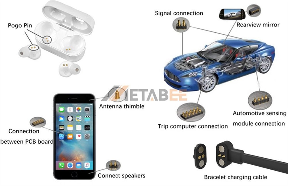
Test and Measurement (A.T.E. Fixtures)
This remains a foundational application. Automated Test Equipment (A.T.E.) and "bed-of-nails" fixtures use arrays of pogo pins to connect quickly and reliably to test points on bare or loaded PCBs. Their high-cycle life ensures the fixture can test thousands of boards before requiring maintenance, making them indispensable for high-volume manufacturing quality control.
Magnetic Charging and Data Transfer
Pogo pins are the standard in modern smartwatches, fitness trackers, and specialized medical devices. By embedding the pogo pins into the charging cradle and using flat contact pads on the device, the connection can be fully sealed and water-resistant. Magnetic docking utilizes the pin's constant spring force to maintain alignment while the magnets provide the mating force, resulting in a durable, user-friendly, and highly protective connection.
Battery Contacts
In many rugged or high-vibration applications—such as drones, industrial scanners, and two-way radios—pogo pins provide the contact interface to the battery pack. Their spring force ensures the battery connection remains stable and low-resistance. This prevents power interruptions or overheating caused by momentary disconnections.
Docking Stations and Cradles
Pogo pins are essential for creating professional docking solutions for rugged tablets, POS terminals, and enterprise communication devices. The design allows for quick, blind mating (docking without looking), as the pins guide the device into place, providing reliable power and network access without fiddly cables.
Board-to-Board Connections
In certain configurations, especially where space is extremely limited or where modules need to be easily swapped, arrays of pogo pins are used to replace conventional two-piece board-to-board connectors. This provides a shock-resistant, high-density connection method in environments requiring high reliability and repairability.
Types and Design Variations
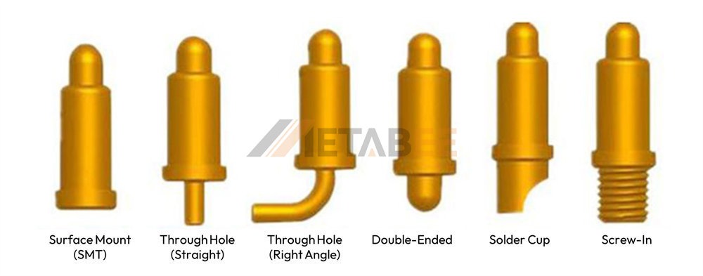
To meet the complex demands of industrial and consumer applications, pogo pins are available in several distinct form factors and specialized designs.
Surface Mount (SMT) Pogo Pins
The Surface Mount design features a flat, solderable bottom cap specifically designed for direct mounting onto the PCB. This is accomplished using standard automated Pick-and-Place machinery and reflow soldering processes. SMT pins are crucial for high-density, automated production, as they eliminate the need for through-hole soldering, saving time and simplifying assembly.
Through-Hole Pogo Pins (Straight and Right-Angle)
These pins are designed with a tail that extends through a hole in the PCB. This configuration provides superior mechanical stability and robustness compared to SMT pins, making them ideal for high-vibration environments. They come in two primary forms: Straight (Vertical) and Right-Angle (Bent). The Straight form maximizes board space, while the Right-Angle form is used for connections parallel to the PCB surface, ideal for edge connectors or specific docking interfaces.
Solder Cup Pogo Pins
This variation features a small concave cup or eyelet at the tail end of the barrel. It is specifically designed for the manual soldering of individual wires or cable assemblies. Solder cup pins are commonly used in prototype development, custom test fixtures, and applications where the pin needs to be terminated to a flexible wire rather than directly to a PCB.
Double-Ended Pogo Pins
These are specialized connectors featuring plungers at both ends. They are primarily used in sophisticated test fixtures, allowing two PCBs (or a fixture and a PCB) to be probed or connected simultaneously. These pins are often used to create a temporary electrical bridge between two vertically stacked components.
Screw-In Pogo Pins
These pins are built with a threaded barrel, allowing them to be screwed into a socket or frame. They offer maximum stability and ease of replacement. This is critical in production testing environments where individual pins may wear out or become damaged and need rapid swapping without dismantling the entire fixture.
High-Frequency / RF Pogo Pins
As data speeds increase, signal integrity becomes paramount. Specialized High-Frequency / RF Pogo Pins are engineered with extremely short spring lengths and optimized internal geometries to ensure a controlled impedance path (often 50 ohms). These are used in applications requiring high bandwidth, such as 5G antenna testing or rapid data transfer from a docked device.
Related Products:
Conclusion
The pogo pin is far more than a simple spring and plunger; it is a high-precision, engineered component. Its unique structure, leveraging gold-plated contacts and the self-cleaning "wiping action," solves some of the most persistent challenges in electronics connectivity. By offering high durability, superior shock resistance, and the capability for high-current transfer in miniature forms, the pogo pin has become an essential component. This functionality is actively shaping the future of industrial, medical, and consumer electronics.
The market is being driven by the growing importance of the Internet of Things (IoT), sophisticated wearable tech, and demanding high-power applications like electric vehicle battery testing. This technological shift means that the demand for customized, high-reliability spring-loaded connectors will only accelerate.
Need a custom spring-loaded connector solution designed for extreme environments, high current, or ultra-low profile? Don’t rely on off-the-shelf components. Contact our engineering team today to discuss a custom pogo pin solution tailored precisely to your next product's specifications.
Alternatively, browse our extensive range of high-quality spring-loaded connector products now and find the standard component that will elevate your design reliability.
Frequently Asked Questions (FAQ)
Q: What is the main functional advantage of the Pogo Pin’s design over traditional connectors?
A: The main advantage is the "wiping action" of the plunger, a self-cleaning mechanism that scrapes away microscopic contaminants and oxide layers during compression. This ensures a consistently low-resistance, reliable electrical connection, even after thousands of cycles.
Q: Why is Gold plating used on Pogo Pins, and what is it plated over?
A: Gold plating is non-negotiable because it offers exceptional chemical stability, which prevents oxidation and maintains low contact resistance. It is plated over a Nickel underplate, which is crucial for enhancing the mechanical durability and structural integrity of the plating.
Q: How does a Pogo Pin maintain connection integrity in high-vibration or shock environments?
A: The internal spring mechanism provides a constant, buffered compression force. This continuous pressure ensures the plunger remains firmly pressed against the contact pad, guaranteeing uninterrupted electrical connectivity during mechanical shock or vibration.
Q: Can Pogo Pins handle high current, and how is this achieved in such a small component?
A: Yes, high-current Pogo Pins (e.g., 10A, 20A+) are available. This capability is achieved through specialized internal designs, often using a "current-carrying sleeve" or internal bypass mechanism that reroutes the current flow away from the high-resistance point of the spring, minimizing heat generation.
Q: What is the typical life cycle of a high-quality Pogo Pin?
A: Due to their robust materials and self-cleaning mechanism, high-quality Pogo Pins are typically rated for an impressive cycle life, ranging from 10,000 up to over 1,000,000 mating cycles.
Q: What role does the Pogo Pin’s spring force play in its reliability?
A: The spring force (measured in grams or ounces) is a critical specification. It is carefully selected to provide sufficient normal force to overcome contaminants and maintain contact, without being so strong that it damages the fragility of the mating surface.
Q: How do Pogo Pins tolerate minor misalignment during device mating?
A: The spring mechanism provides a built-in tolerance for slight axial and radial inconsistencies. The plunger tip is designed to smoothly guide itself into contact, which simplifies the user experience and prevents physical damage often caused by fixed-pin connectors.
Q: What are the 3 essential components of a Pogo Pin?
A: A Pogo Pin is a three-part electromechanical component: the Plunger (the moving contact tip), the Barrel (the rigid housing and guide), and the Spring (which provides the compression force).
Q: How are Pogo Pins used in devices that require water resistance, like smartwatches?
A: In devices like smartwatches and fitness trackers, Pogo Pins are typically embedded in a charging cradle. The use of flat contact pads on the device allows the device's connection area to be fully sealed, making the overall product design highly water-resistant.
Q: When should I consider a custom Pogo Pin solution rather than an off-the-shelf component?
A: Custom solutions are often necessary for demanding applications like extreme operating environments, specific high-current or high-frequency (RF) requirements. They are also needed when the design calls for an ultra-low profile or miniature form factor not available in standard offerings.
