
The RJ45 connector is the standard 8P8C (8-position, 8-contact) interface used to terminate Ethernet cables and establish wired network connections. If you'd like to learn more about its physical structure, dimensions, and connector types, see our guide: What Is an RJ45 Connector?
Whether you're installing structured cabling, building a home network, or troubleshooting an Ethernet connection, understanding the RJ45 pinout is essential. Even a small wiring mistake can result in connectivity issues, reduced network speeds, or unreliable PoE performance.
In this guide, you'll learn the complete RJ45 pinout diagram, compare T568A and T568B wiring standards, understand RJ45 plug and jack pin orientations, and discover best practices for terminating and testing Ethernet cables correctly.
RJ45 Connector Pinout:T568A & T568B Standards
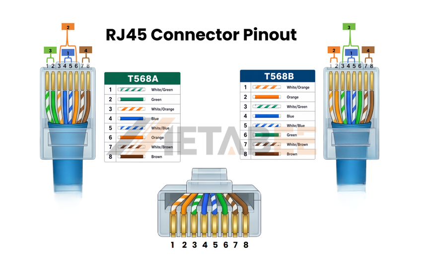
To resolve immediate technical inquiries and serve as an instant field reference, this section highlights the TIA/EIA standard configurations. The Telecommunications Industry Association (TIA) and Electronic Industries Alliance (EIA) define two primary color-coded standards for terminating twisted-pair Ethernet cables: T568B and T568A.
T568B is the default standard for the vast majority of commercial and residential structured cabling deployments throughout North America, Europe, and Asia. T568A is primarily utilized in US government installations, military infrastructure, specific legacy telephone system integrations, and compliance-mandated residential wiring schemes under standard ANSI/TIA-570-D.
The Ultimate RJ45 Pinout Reference Table
Below is the highly detailed, upgraded 4-column master table documenting the exact rj45 connector pin details. It maps physical pin locations, standard differential signal nomenclature, high-frequency baseband assignments, and both the T568B and T568A rj45 wiring color code standards.
|
Pin Number |
Signal name |
T568B Color |
T568A Color |
Electrical Signal& Phase Role |
|
Pin 1 |
TX+/BI_DA+ |
White/Orange |
White/Green |
Transmit/Receive |
|
Pin 2 |
TX-/BI_DA- |
Orange |
Green |
Transmit/Receive |
|
Pin 3 |
RX+/BI_DB+ |
White/Green |
White/Orange |
Transmit/Receive |
|
Pin 4 |
Spare/BI_DC+ |
Blue |
Blue |
Unused(Spare) in 10/100 Mbps |
|
Pin 5 |
Spare/BI_DC- |
White/Blue |
White/Blue |
Unused(Spare) in 10/100 Mbps |
|
Pin 6 |
RX-/BI_DB- |
Green |
Orange |
Transmit/Receive |
|
Pin 7 |
Spare/BI_DD+ |
White/Brown |
White/Brown |
Unused(Spare) in 10/100 Mbps |
|
Pin 8 |
Spare/BI_DD- |
Brown |
Brown |
Unused(Spare) in 10/100 Mbps |
Technical Note:10/100 Mbps Ethernet uses only Pins 1, 2, 3, and 6, whereas Gigabit and 10 Gigabit Ethernet use all eight conductors. PoE-enabled networks can also deliver power through these same cable pairs while maintaining normal data transmission.
How Differential Signaling Cancels Interference
To understand why each wire color must be assigned to a specific pin, it is important to understand how Ethernet reduces electrical interference. Ethernet networks rely on differential signaling transmitted over twisted wire pairs.
Rather than carrying data on a single conductor, Ethernet sends two complementary signals across a twisted pair. One wire carries the original signal, while its partner carries an inverted version of the same signal.
Because the two conductors are tightly twisted together, they are exposed to nearly identical external electromagnetic interference (EMI) and radio-frequency interference (RFI) along the cable path. At the receiving device, the two signals are compared and recombined. Any noise that appears equally on both conductors is effectively canceled out, while the intended data signal is preserved.
This is why maintaining the correct wire pair assignments is critical. If conductors from different pairs are mixed together—for example, pairing White/Orange with Green instead of Orange—the cable loses the benefits of differential signaling and pair twisting. The result can be increased crosstalk, reduced signal integrity, lower network performance, and intermittent connectivity issues.
T568A vs T568B RJ45 Pinout: What's the Difference?
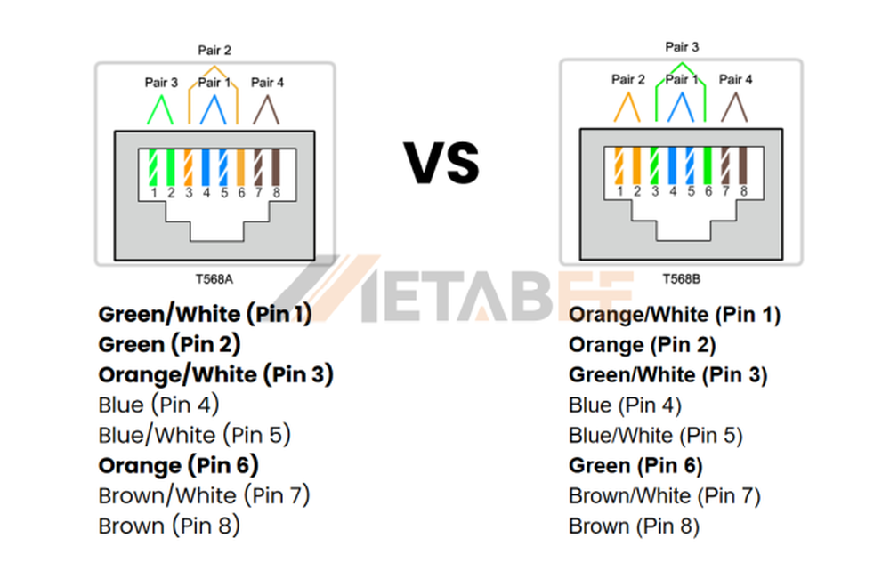
When wiring an RJ45 Ethernet cable, the two recognized wiring standards are T568A and T568B. The only physical difference between these standards is the placement of the orange and green wire pairs. Despite this small variation, both pinouts deliver identical Ethernet performance when terminated correctly.
T568A vs T568B difference in wire arrangement
T568A and T568B are the two standardized Ethernet wiring schemes defined by ANSI/TIA-568. The only difference between them is the position of the Orange pair and Green pair:
T568A: Pair 2 = Green, Pair 3 = Orange
T568B: Pair 2 = Orange, Pair 3 = Green
T568A vs T568B in application
Although T568A and T568B provide identical Ethernet performance, they were originally designed for different deployment environments.
- T568A (Backward Compatible with USOC): T568A maintains compatibility with the legacy USOC (Universal Service Ordering Code) telephone wiring standard. Its pin assignments align more naturally with traditional voice systems, allowing easier integration of both telephone and data services within the same structured cabling infrastructure. For this reason, T568A is commonly specified in residential installations and remains a requirement in certain government, military, and ANSI/TIA-570 compliant projects.
- T568B (Optimized for Pure Data): T568B, originally derived from the AT&T 258A wiring scheme, was developed primarily for Ethernet networking. Because it is optimized for modern data communications rather than legacy telephone compatibility, T568B became the dominant standard in commercial offices, enterprise networks, and data centers. Today, most pre-terminated Ethernet patch cables and structured cabling systems follow the T568B pinout.
Summary Table
|
Category |
T568A |
T568B |
|
Pair 2 |
Green |
Orange |
|
Pair 3 |
Orange |
Green |
|
Legacy Telephone compatibility |
Better |
Lower |
|
Typical Application |
Residential Networks |
Commercial Networks |
|
Common Usage Today |
Less Common |
Most Common |
|
Ethernet Speed |
Same |
Same |
|
PoE Support |
Same |
Same |
RJ45 Plugs vs. RJ45 Jacks: Understanding the Mirrored Pin Layout
The T568A and T568B wiring schemes discussed above describe the pinout of an RJ45 plug, where the eight conductors are arranged in a clearly visible left-to-right sequence. When terminating an Ethernet cable, installers simply follow this conductor order to ensure the correct pin assignments.
Standard RJ45 Jack Pinout: Mirrored Contact Layout
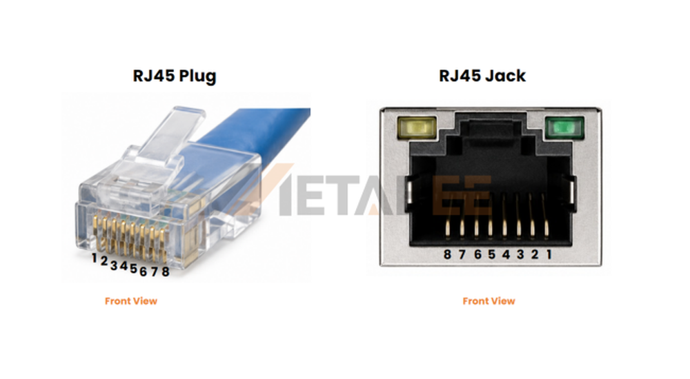
The pinout of a standard RJ45 jack is often less intuitive than that of an RJ45 plug. Unlike a plug, an RJ45 female jack uses a mirrored contact layout internally. This design is intentional and allows the spring contacts inside the jack to align correctly with the contacts on the inserted RJ45 plug. As a result, when viewed from the front opening of the jack, the contacts appear to be arranged in reverse order compared to the plug.
Despite this apparent reversal, the electrical pin numbering remains unchanged. Pin 1 on the plug still mates with Pin 1 on the jack, Pin 2 connects to Pin 2, and so on through Pin 8. The mirrored appearance is purely a consequence of the jack's mechanical contact geometry and should not be confused with a reversed electrical pinout.
Source Quality RJ45 Connectivity Solutions
Correct RJ45 pinouts are only part of a reliable network. High-quality connectors and modular jacks are equally important for maintaining stable performance and long-term durability. Metabee offers RJ45 connectors, modular jacks, and custom connectivity solutions for commercial and industrial applications. Contact our team today for technical support, volume pricing, and customized quotations.
RJ45 Ethernet Cable Pinout Configurations: Straight-Through vs. Crossover
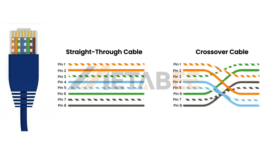
How you combine these two T568A/B standards on each end of the cable determines the type of Ethernet cable you create. For everyday networking, there are only two essential configurations you need to understand:
Straight-Through Cable (Pin-to-Pin Mapping)
A straight-through cable (often called a patch cord) acts as a direct, parallel bridge where Pin 1 connects to Pin 1, Pin 2 to Pin 2, and so forth. This is the standard network cable used in 99% of daily applications.
The Wiring: Both ends of the cable are wired using the exact same standard. In modern setups, you should always use T568B on both End A and End B. (Using T568A on both ends also works, but T568B is the universal default).
How It Works: Since network routers and switches have internal hardware designed to handle traffic routing, the cable itself only needs to carry the signal straight through without swapping paths.
Daily Applications (Connecting Different Devices):
- Connecting a Computer, Laptop, or Gaming Console to a Network Switch, Router, or Wall Jack.
- Connecting a Smart TV or Streaming Box to a home router.
- Connecting a Router's WAN Port to your Fiber/Cable Broadband Modem.
Crossover Cable (Tx-to-Rx Physical Swap)
A crossover cable physically crosses the transmit (TX) signals of one device to the receive (RX) signals of another. This allows two similar devices to communicate directly without a middleman (like a router or switch).
The Wiring: One end of the cable is wired with T568B, and the other end is wired with T568A. This configuration swaps the green and orange pairs, redirecting Pins 1 & 2 on one end to Pins 3 & 6 on the other end.
Daily Applications (Connecting Similar Devices Directly):
- Directly connecting Computer to Computer to transfer files at maximum speed without a router or Wi-Fi.
- Linking two Xbox or PlayStation consoles together for a lag-free, offline LAN gaming party.
- Connecting two legacy Network Switches together to expand your network ports.
Why You Rarely Need to Make One Today (Auto-MDIX):
Almost all modern network devices feature a technology called Auto-MDIX (Automatic Medium-Dependent Interface Crossover). This smart feature automatically detects the connection type and swaps the transmission and reception paths electronically inside the network chip. Because of Auto-MDIX, you can use a standard straight-through cable for direct PC-to-PC setups today, making physical crossover cables almost entirely obsolete!
RJ45 Pinout for PoE Applications
Power over Ethernet (PoE) allows a standard Ethernet cable to carry both network data and electrical power through the same RJ45 connection. This technology eliminates the need for separate power supplies, making it easier to deploy devices such as IP cameras, VoIP phones, wireless access points, access control systems, and industrial IoT equipment.
One common misconception is that PoE requires a different RJ45 pinout. In reality, the standard RJ45 pin assignments remain unchanged. Whether a cable is used for conventional Ethernet networking or PoE, the connector still follows the same T568A or T568B wiring scheme. The difference is that PoE uses specific wire pairs within the existing RJ45 pinout to deliver DC power alongside data signals.
Depending on the PoE implementation, power may be delivered through different wire pairs. Earlier PoE systems typically used either the Orange and Green pairs (Pins 1, 2, 3, and 6) or the Blue and Brown pairs (Pins 4, 5, 7, and 8). Modern PoE++ (IEEE 802.3bt) systems distribute power across all four twisted pairs, allowing significantly higher power levels for devices such as PTZ cameras, digital signage displays, and high-performance wireless access points.
|
PoE Method |
Wire Pair Used for Power |
|
Mode A |
Pins 1,2,3, and 6(orange&green pairs) |
|
Mode B |
Pins 4,5,7, and 8(blue&brown pairs) |
|
PoE++(4-pair PoE) |
All four twisted pairs |
The key point to remember is that PoE does not introduce a special RJ45 wiring pattern. A correctly terminated T568A or T568B cable can support both data transmission and power delivery simultaneously. The RJ45 pin numbering never changes; only the way network equipment uses the existing wire pairs changes depending on the PoE standard and power requirements.
How to wire an RJ45 Connector?
Terminating an RJ45 connector is a highly practical skill. Whether you are expanding a home laboratory or repairing a snapped clip on an office patch cord, following a structured process ensures maximum throughput.
Wiring tool
Before starting your DIY cabling project, gathering the correct, high-quality tools will save you time and prevent ruined connectors.
- Ethernet Cable: Cat5e, Cat6, or Cat6A bulk twisted-pair cable (solid copper is preferred for structural runs; stranded copper for patch cords).
- RJ45 Connectors (Plugs): Make sure your connectors match your cable category (e.g., Cat6 plugs for Cat6 cable).
- Pro Tip: Pass-Through RJ45 Connectors are highly recommended for beginners. They allow wires to feed completely through the front of the plug, making color-code verification much easier before crimping.
- RJ45 Crimping Tool: A heavy-duty ratcheting crimper. If using pass-through plugs, ensure your crimper has a built-in flush-trimming blade.
- Cable Jacket Stripper: For cutting the outer PVC sheath without scoring the inner insulation of the copper pairs.
- Flush Cutters / Scissors: For trimming the internal plastic spline (separator) and cutting conductors cleanly.
- Network Cable Tester: A basic continuity tester to verify pin-to-pin mapping after termination.
Step-by-step Guide
Now that you know the theory and have your tools ready, follow these detailed steps to terminate your own high-performance Ethernet cable using the T568B standard.
Step 1: Prepare the Cable
Before making any cuts, slide the strain relief boot onto the Ethernet cable if one will be used. This is a common step that is often forgotten and cannot be added after the RJ45 connector has been crimped. Once the boot is in place, prepare your cable stripper and RJ45 connector for termination.
Step 2: Strip the Outer Jacket
Use a cable stripper to remove approximately 1.5 inches (38 mm) of the outer jacket, exposing the four twisted pairs inside. Take care not to damage the insulation of the individual conductors, as even minor nicks can affect network performance and long-term reliability.
Step 3: Separate and Straighten the Conductors
Untwist the four wire pairs and arrange the conductors so they can be easily organized into the required pinout sequence. If the cable contains a plastic spline or separator, trim it flush with the jacket. Straightening the wires at this stage will make the next steps much easier and help ensure accurate alignment.
Step 4: Arrange the Wires According to T568B
Organize the eight conductors into the T568B color sequence: White/Orange, Orange, White/Green, Blue, White/Blue, Green, White/Brown, and Brown. Hold the wires firmly between your fingers and verify the color order before proceeding, as correcting mistakes becomes more difficult once the connector is installed.
Step 5: Trim and Insert the Wires
Trim the conductors evenly so they are all the same length, then carefully insert them into the RJ45 plug. Each wire should slide fully into its designated channel, and the cable jacket should extend into the rear of the connector to provide proper strain relief after crimping.
Step 6: Verify and Crimp the Connector
Before crimping, perform a final visual inspection to confirm the wire sequence matches the T568B pinout. Once verified, insert the connector into the crimping tool and compress it firmly to secure the contacts and locking tab. After crimping, check that all conductors remain correctly positioned and fully seated inside the connector.
How to Verify Your RJ45 Pinout
After crimping an RJ45 connector, it is important to verify that the cable has been terminated correctly before putting it into service. Even a single misplaced conductor can prevent the cable from functioning properly or reduce network performance.
The simplest method is a visual inspection. Hold the RJ45 plug with the contacts facing toward you and confirm that the wire colors appear in the correct T568A or T568B sequence. Also check that all eight conductors reach the front of the connector and that the cable jacket is securely captured inside the plug for proper strain relief.
For a more reliable test, use an Ethernet cable tester. Connect each end of the cable to the tester and verify that all eight pins map correctly from one end to the other. If a pin fails to light up, the cable may contain an open connection. If the tester indicates that pins are mapped to the wrong locations, the conductors were terminated in the incorrect order and the connector should be re-crimped.
Common RJ45 Wiring Mistakes
Even experienced installers occasionally make wiring mistakes. The following issues are among the most common causes of Ethernet cable failures.
Split Pairs
A split pair occurs when the correct pin numbers are used but the conductors from a twisted pair are mixed with wires from another pair. Although the cable may appear correct and even pass a basic continuity test, network performance can be severely degraded due to increased interference and crosstalk. Always follow the T568A or T568B color sequence exactly as specified.
Excessive Pair Untwisting
Twisted pairs are designed to reduce electromagnetic interference and maintain signal integrity. Untwisting the conductors too far before termination can negatively affect performance, especially on higher-speed networks. For best results, keep the twists as close to the RJ45 connector as possible.
Improper Strain Relief
The outer cable jacket should extend into the rear of the RJ45 plug and be secured by the strain relief tab during crimping. If only the individual conductors are captured, the cable becomes much more susceptible to damage when pulled, bent, or repeatedly handled.
Conclusion
This guide explains how to wire RJ45 connectors using the T568A and T568B standards, the two accepted Ethernet pinout configurations. Because Ethernet relies on precise wire-pair assignments for reliable data transmission and PoE delivery, correct termination is essential for network performance.
You'll learn how to prepare, arrange, crimp, and test Ethernet cables, as well as how to identify common wiring errors such as incorrect pin mapping and split pairs. For high-volume projects or custom connectivity requirements, Metabee also provides professional RJ45 connectivity solutions and technical support.
Need Professional Support? Consult the Metabee Team
If you are planning a large-scale network upgrade, building a high-speed smart home laboratory, or designing a complex Power over Ethernet (PoE) deployment for your enterprise, our professional team is here to assist you.
We provide certified bulk network solutions, reliable patch cords, and industry-leading modular connectors tailored to your unique requirements. Welcome to consult our professional Metabee technical support team for customized product recommendations, engineering support, and reliable network hardware solutions.
Related Products
Cat5E Cables
Cat6 Cables
Cat6A Cables
Related Post
What is an RJ45 8P8C Connector?
What is an RJ45 with Integrated Magnetics?
RJ45 Connectors Shielded vs Unshielded
FAQ
Q: What is the difference between T568A and T568B pinouts?
A: They only differ in the green and orange wire placements. T568A puts the green pair on pins 1 & 2 and the orange pair on pins 3 & 6, while T568B reverses this layout. Both standards deliver identical high-speed data performance.
Q: Can I mix T568A and T568B standards within the same home network?
A: Yes, provided each individual cable uses the same standard on both ends. Mixing T568A and T568B on opposite ends of a single cable creates a crossover cable. However, using T568A cables alongside T568B cables in the same patch panel will not impact network operations.
Q: Why has my DIY Gigabit cable dropped down to 100 Mbps?
A: An unfinished or loose connection on pins 4, 5, 7, or 8 is the usual cause. 10/100 Mbps Fast Ethernet only requires four wires (pins 1, 2, 3, and 6) to run, whereas Gigabit Ethernet demands all eight wires to function correctly. If any single wire lacks solid contact, the network automatically throttles down to 100 Mbps.
Q: What is a split pair error, and why is it problematic?
A: It is when wires from different physical twisted pairs are wrongly paired to complete a circuit pin-to-pin. Although a simple continuity tester will show a successful connection, splitting the pairs destroys the electromagnetic noise-canceling effects, creating massive high-frequency crosstalk and severe data loss.
Q: Are pass-through RJ45 connectors better than standard closed-end connectors?
A: Yes, they are much easier for beginners and significantly reduce termination errors. Pass-through plugs let you slide the individual wires completely out the front end so you can visually verify the exact color sequence before squeezing the crimping tool.
Q: Can I use Cat6 connectors on a thicker Cat6A cable?
A: No, Cat6A wires are generally too thick to fit into standard Cat6 plugs. Cat6A cables feature thicker copper conductors and heavy-duty insulation. Attempting to force them into a smaller Cat6 connector will ruin the cable alignment or fail to make proper physical contact.
Q: Is Solid Copper Ethernet cable better than Stranded Copper?
A: Yes, solid copper is significantly better for permanent installations and PoE. Solid copper offers lower electrical resistance, making it perfect for long runs inside walls and high-power PoE distribution, while stranded copper is flexible and ideal for short patch cords.
Q: Does stripping off too much outer jacket damage my network performance?
A: Yes, it exposes the wires to external noise and mechanical tension. Stripping back too much protective jacket untwists the internal copper pairs. Under TIA standards, you must keep the outer sheath firmly inside the plug under the strain relief tab to prevent interference.
Q: What happens if I forget to slip on the strain relief boot before crimping?
A: You will have to cut off the connector and crimp a new one if you absolutely need the boot. The boot must be threaded onto the cable before termination. While the cable will still function without it, the boot helps protect the locking tab and extends the cable life.
Q: How do PoE networks send power safely without burning out non-PoE devices?
A: They use a smart handshake negotiation process called PoE detection. The power sourcing equipment (PSE) sends a tiny initial voltage to verify if the receiving device is PoE-compatible. If no signature is detected, the switch runs standard data-only mode, keeping non-PoE devices completely safe.
