
Are you struggling to fit complex power, RF, and signal lines into an increasingly shrinking device footprint? As modern electronics demand higher efficiency in tighter spaces, traditional wiring methods often fall short. This comprehensive guide explores the structural anatomy, critical technical specifications, and diverse industry applications of Combo D-Sub connectors. Whether you are an electronics engineer designing compact medical devices or a procurement manager sourcing robust industrial components, this article provides the necessary insights. Our goal is to help you select the perfect mixed-layout interconnect solutions to streamline your next demanding project.
Introduction to Combo D-Sub Connectors
What is a Standard D-sub Connector?
Standard D-Sub (short for D-subminiature) connectors have served the electronics industry for decades. You recognize them by their iconic D-shaped metal shield. This metallic shell provides mechanical support and ensures correct mating orientation. Historically, standard D-Subs transmitted low-level signal data. They feature multiple rows of standard machine or stamped pins. Early computers and serial communication systems relied heavily on these reliable interconnects.
Related Post:
What is D-Sub? A Comprehensive Guide to D-Sub Connectors
41 D-Sub Connector Types Explained and Selecting the Right D-Sub Connector in 3 Steps
What Makes a Combo D-Sub Different?
A Combo or Combination D-Sub connector is a hybrid interface that combines standard signal pins with high-current, coaxial, or high-voltage contacts in one shell. This design represents a significant evolutionary step. It takes the classic D-shaped shell and modifies the internal layout. You no longer just transmit basic signals. This consolidation drastically saves printed circuit board (PCB) space. You reduce your cable count and simplify your overall system architecture.
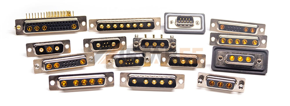
Metabee Combo D-sub Connectors
Key Industry Standards and Compliance
Reliability remains non-negotiable in any engineering project. Quality Combo D-Sub connectors must meet strict global standards. The MIL-DTL-24308 specification dictates rigorous military-grade performance requirements. Connectors must endure extreme vibrations and temperature fluctuations. Safety is also paramount. Underwriters Laboratories (UL) ratings certify the fire safety and electrical integrity. Furthermore, Metabee engineers ensure all interconnect solutions comply strictly with RoHS and REACH directives. This guarantees the materials contain no hazardous substances.
Structural Anatomy and Material Compositions
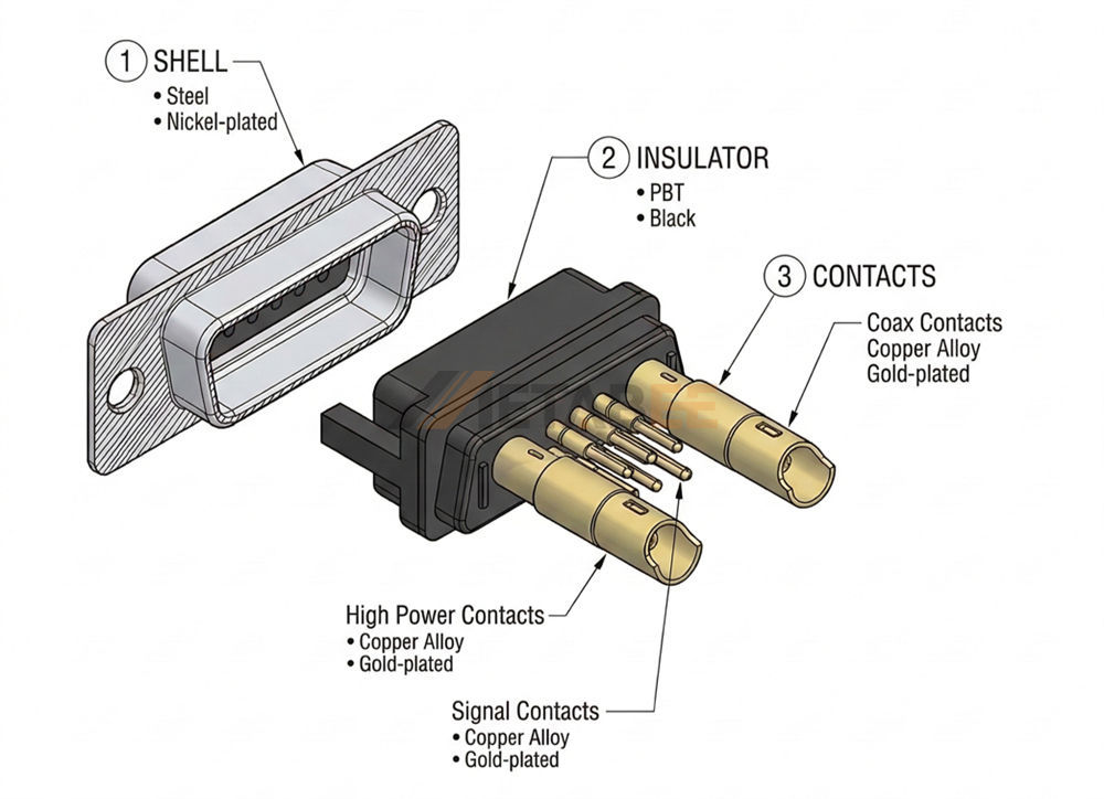
Understanding the internal construction helps you make better purchasing decisions. Manufacturers engineer these connectors using premium materials to guarantee long-term performance.
Shell Construction and Shielding
The outer shell serves as the first line of defense. Manufacturers typically stamp shells from steel or brass. They then apply specific plating materials to enhance durability. Tin plating offers excellent solderability and basic corrosion resistance. Nickel plating provides superior wear resistance for high-mating environments. Gold plating over nickel delivers the ultimate defense against harsh elements. These metal shells also provide crucial EMI/RFI shielding. They block electromagnetic interference from disrupting sensitive data transmissions.
High-Performance Insulator Materials
The insulator holds the complex pin layout perfectly in place. It must prevent electrical shorts between tightly packed contacts. Manufacturers inject glass-filled thermoplastics to create these critical components. Polybutylene Terephthalate (PBT) and Liquid Crystal Polymer (LCP) are highly popular choices. These materials exhibit exceptional dielectric strength. They withstand the extreme heat generated during wave soldering processes. They also maintain their structural integrity in high-temperature operating environments.
The Three Core Contact Types: Signal, High-Current, and Coaxial
The true power of a Combo D-Sub lies in its contact versatility. You can mix and match three primary contact types.
Signal Contacts: These handle standard, low-level data transmission. Manufacturers make them from durable copper alloys. They usually feature gold-over-nickel plating to ensure low contact resistance.
High-Current (Power) Contacts: Systems need reliable power delivery. High-current contacts manage significant electrical loads. Metabee designs premium power contacts that efficiently dissipate heat. They feature heavy gold plating to maximize conductivity and prevent oxidation.
Coaxial Contacts: You need these for radio frequency (RF) and video signals. These micro-coaxial designs feature a center conductor and an outer shield. They ensure clean, lossless transmission for high-frequency data applications.
Shell Sizes and Contact Arrangements (Layouts)
You must select the correct physical size and pin layout for your project. The industry uses standardized sizing to ensure compatibility.
Standard Shell Sizes (E, A, B, C, D)
Combo D-Subs utilize the same exterior shell dimensions as standard D-Subs. The industry categorizes these sizes from E (the smallest) to D (the largest).
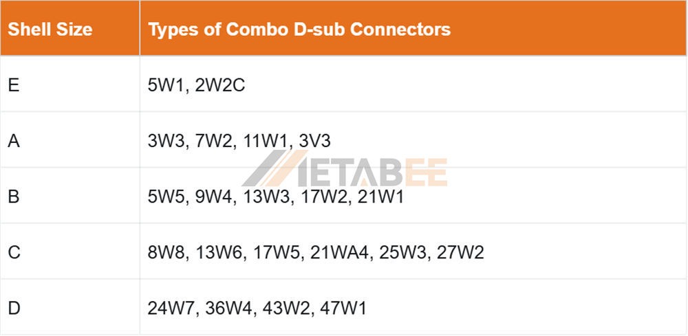
Combo variants keep these exterior shell dimensions. However, they completely reconfigure the internal insulator space to accommodate the larger special contacts.
Popular Pinout Configurations
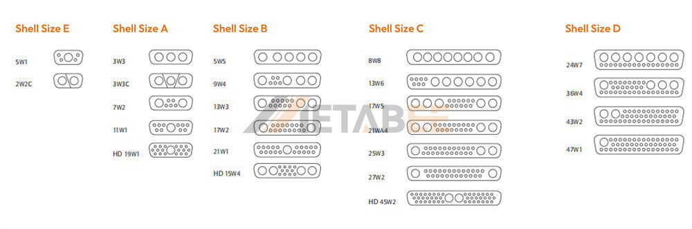
Engineers use specific alphanumeric codes to identify the contact layout. You will frequently see configurations like 3W3, 7W2, 13W3, and 21WA4. Let us break down what these numbers mean. The first number indicates the total number of contacts. The "W" stands for "Work" or mixed contacts. The final number tells you how many of those contacts are special (power or coax). For example, a 7W2 layout fits into a Size A shell. It contains 7 total contacts. Five of those are standard signal pins. The remaining two are large special cavities for power or coaxial contacts. A 3W3 layout contains exactly three special contacts and zero signal pins.

The Combo D-Sub connector pinout configurations are shown below.
Critical Technical Specifications
You must evaluate specific technical parameters before finalizing your bill of materials. Pay close attention to electrical, mechanical, and environmental ratings.
Electrical Characteristics
Electrical capacity dictates the connector's fundamental capability. Standard signal contacts typically handle up to 5 amps of current. High-current power contacts offer much greater capacity. They carry 10 amps, 20 amps, and 40 amps per pin. Coaxial contacts support frequencies up to 500 MHz or more. You must also verify the dielectric withstanding voltage. High-quality connectors easily withstand 1000 VAC without breaking down or shorting.
Mechanical Durability
Industrial applications often require frequent connection and disconnection. You measure a connector's mechanical lifespan in mating cycles. Standard commercial connectors survive around 100 to 200 mating cycles. High-reliability industrial versions guarantee 500 or more mating cycles. You should also evaluate the insertion and extraction forces. The connector must mate smoothly but hold securely to prevent accidental disconnections.
Environmental Performance and IP Ratings
Industrial connectors face punishing environments daily. They must operate flawlessly in extreme temperatures. A standard operating range spans from -55°C to +125°C. Moisture and dust present significant threats to electrical integrity. Manufacturers solve this by adding silicone O-rings and specialized epoxy seals. You can easily procure IP67-rated waterproof Combo D-Subs. Engineers deploy these ruggedized versions in outdoor telecom towers and maritime equipment.
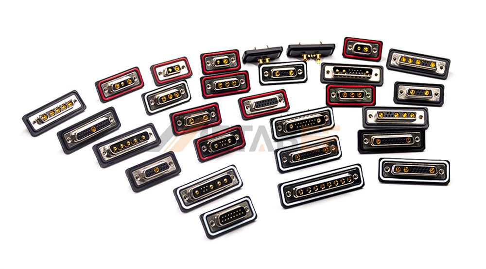
Metabee Waterproof Combo D-sub Connectors
Technical Specifications Summary
|
Specification Parameter |
Typical Performance Range |
|
Signal Contact Current |
Up to 5 Amps |
|
Power Contact Current |
10A to 40A+ (Up to 50A customized) |
|
Coaxial Frequency Range |
Up to 500 MHz |
|
Dielectric Withstanding Voltage |
1000 VAC |
|
Mechanical Mating Cycles |
500+ |
|
Operating Temperature |
-55°C to +125°C |
|
Environmental Protection |
Up to IP67 (Waterproof options available) |
Major Industry Applications
Various demanding industries rely on these versatile interconnects. They solve complex engineering challenges across multiple sectors.
Industrial Automation and Motor Control
Modern factory floors utilize advanced robotics and servo motors. These machines require simultaneous power delivery and precise sensor feedback. A Combo D-Sub handles both tasks through a single cable. You reduce cable clutter on moving robotic arms. This prevents cable fatigue and significantly reduces factory downtime.
Medical Diagnostic and Imaging Equipment
Medical devices demand absolute precision and zero failure rates. MRI machines and ultrasound diagnostic equipment process massive amounts of data. They also require clean, stable power. Combo D-Sub connectors deliver this critical mixed-signal performance. They ensure high-frequency imaging data travels without EMI disruption. Their compact nature also helps engineers design sleeker, more portable medical carts.
Aerospace, Defense, and Telecommunications
Space constraints define aerospace engineering. Avionics systems must remain incredibly compact and lightweight. Combo D-Sub connectors save crucial space inside aircraft control panels. Defense contractors use military-spec versions for ruggedized communication gear. Telecommunication companies deploy them inside cellular base stations. They reliably route power and RF signals to sensitive antenna arrays.

Selection Guide: Choosing the Right Combo D-Sub
Selecting the perfect connector requires careful project analysis. You must match the connector specifications to your exact system requirements.
Defining Your Power and Signal Ratio
Evaluate your power and signal requirements first. Map out exactly how many data lines you need. Calculate the peak amperage required for your power delivery. This simple audit dictates your ideal pinout configuration. If you need robust power and minimal data, select a 3W3 layout. If you need extensive sensor data and minimal power, a 21WA4 layout works best.
Selecting the Right Termination Method
How will you attach the connector to your cable or board? Metabee offers diverse termination options to match your manufacturing capabilities.
- Solder Cup: Workers manually solder individual wires into small metallic cups. This suits low-volume or custom cable assemblies perfectly.
- PCB Mount: You solder the connector directly to the circuit board. You can choose straight pins for vertical mounting. You can choose right-angle pins for edge-mounting.
- Crimp Termination: Operators use specialized tools to crush metal pins onto bare wires. You then snap the pins into the connector body. This method enables rapid, high-volume production.
Mounting Hardware and Accessories
Never overlook the importance of secure mounting hardware. Connectors can vibrate loose in industrial settings. You must specify the correct locking mechanisms. Jackscrews securely bolt the mating connectors together. Board locks firmly anchor the connector to the PCB before wave soldering. Finally, you should pair your connector with a durable metal or plastic backshell. Backshells provide essential strain relief for the attached cables.
Conclusion
Combo D-Sub connectors represent a brilliant feat of electrical engineering. They elegantly combine power, signal, and coaxial contacts into one familiar shell. You immediately save valuable PCB real estate by utilizing them. You lower your assembly costs by reducing total cable counts. Upgrading to a mixed-layout connector streamlines your entire system architecture.
Partner with Us for Custom Interconnect Solutions
Do you need help selecting the perfect mixed-layout connector for your next project? Metabee specializes in high-performance electronic connectors and custom wire harnesses. Our engineering team will help you configure the exact pinout and termination style you need.
Contact us today to request product samples, review technical drawings, and get a custom quote for your project!
Related Products
- Combo D-sub Connectors
- Waterproof D-sub Connectors
- Standard D-sub Connectors
- High-density D-sub Connectors
Frequently Asked Questions (FAQs)
Q1: Can I mix high-current and coaxial contacts in the same connector?
A: Yes, you absolutely can. Metabee offers custom contact layouts. You can specify a configuration that houses signal, power, and coaxial contacts simultaneously.
Q2: What is the maximum current a Combo D-Sub power contact can handle?
A: Standard high-current contacts usually handle 10, 20, or 40 amps. Some specialized heavy-duty contacts can manage up to 50 amps depending on the wire gauge used.
Q3: Are Combo D-Sub connectors backward compatible with standard D-Subs?
A: No, you cannot mate them together. While the exterior shell dimensions match, the internal pin layouts differ entirely. A standard D-sub plug will physically collide with the large power receptacles of a combo D-sub.
Q4: Do I need special tools to crimp and extract contacts from a Combo D-Sub?
A: Yes, while standard signal pins use standard D-Sub crimping tools, the larger high-current and coaxial contacts require specific crimp dies and extraction tools designed for their exact cavity sizes.
Q5: Can Combo D-Sub connectors operate reliably in high-vibration applications?
A: Absolutely. When paired with appropriate mounting hardware like locking jackscrews and ruggedized metal backshells, these connectors easily withstand the intense vibrations found in aerospace and heavy industrial machinery.
Q6: What is the difference between machined and stamped contacts in these connectors?
A: Machined contacts are turned from solid brass or copper alloy, offering superior durability, higher current capacity, and more mating cycles. Stamped contacts are formed from sheet metal, providing a cost-effective solution for less demanding commercial applications.
