
Pogo pins are compact spring-loaded electrical contacts designed to provide reliable connections between two mating surfaces. They are widely used in electronic devices where a secure electrical connection, repeated mating, or a compact contact solution is required.
As electronic products become smaller and more integrated, pogo pins are available in different mounting methods and configurations to meet various mechanical and electrical requirements. Common options include surface mount (SMT), through-hole (THT), right-angle, solder cup, double-ended, and side-mount pogo pins.
However, choosing the wrong pogo pin type can lead to poor connectivity, mechanical failure, and costly redesigns. In this comprehensive guide, we will break down exactly how pogo pins work, explore the 5 most common types and mounting styles, and provide actionable tips on how to choose the perfect spring-loaded connector for your specific application. Let's dive in.
What is a Pogo Pin?
Understanding the basic structure of a pogo pin is the first step toward understanding how it works and how different types are designed for specific applications. This section covers the definition of a pogo pin and the key components that make up its spring-loaded contact mechanism.
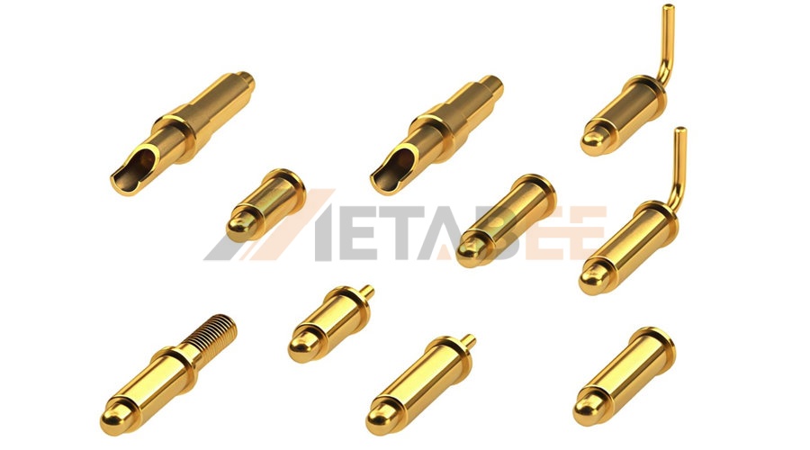
Definition
A pogo pin is a spring-loaded electrical contact designed to maintain reliable electrical connections between mating surfaces. It typically consists of a plunger, spring, and barrel, with the internal spring providing contact force when the plunger is compressed.
Unlike conventional fixed contacts, its spring-loaded structure allows the contact point to move under compression while maintaining a consistent contact force. This flexibility enables pogo pins to accommodate small variations in the position or height of mating surfaces, making them particularly suitable for applications that require repeated mating, reliable electrical contact, or limited installation space.
Pogo pins are available in various mounting methods and configurations to meet different mechanical and electrical requirements. Depending on the application, they can be designed for PCB mounting, wire connections, angled contacts, or connections between two mating surfaces. These variations allow pogo pins to be used across a wide range of electronic products and systems, including consumer electronics, charging devices, wearable devices, industrial equipment, and test equipment.
Pogo Pin Structure
A typical pogo pin consists of several precisely assembled components that work together to provide both mechanical movement and electrical continuity. The main components include the plunger, spring, and barrel, while the contact tip and mounting termination may vary depending on the specific design.
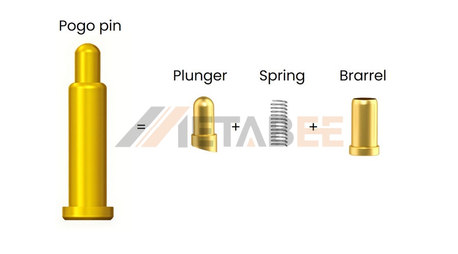
Plunger
The plunger is the movable component located at the top of the pogo pin. It directly contacts the mating surface and moves inward when an external force is applied. The plunger is typically made from a conductive metal and may feature different contact-tip shapes depending on the application.
Spring
The spring is located inside the barrel and provides the mechanical force needed to keep the plunger pressed against the mating surface. When the plunger is compressed, the spring stores mechanical energy and generates a restoring force.
Barrel
The barrel is the outer body that houses and guides the internal components. It keeps the spring and plunger properly aligned while allowing the plunger to move smoothly during compression and release.
Together, these components allow a pogo pin to combine electrical conductivity with controlled mechanical movement. The plunger provides the mating contact, the spring generates contact force, and the barrel supports and guides the internal mechanism, while the contact tip and termination structure can be adapted to different applications and installation requirements.
How Do Pogo Pins Work?
Pogo pins use a simple spring-loaded mechanism to maintain reliable electrical contact between mating surfaces. When a mating surface presses against the plunger, the plunger moves into the barrel and compresses the internal spring. The spring then generates a restoring force that keeps the plunger pressed against the mating surface, helping maintain stable electrical continuity even when there are small variations in the mating position.
As the mating surface is removed, the spring returns the plunger to its original position, allowing the pogo pin to reset for the next connection. This repeated compression and release makes pogo pins particularly suitable for applications that require frequent mating and unmating.
The basic working process can be summarized as:
Contact → Plunger Compression → Spring Force → Electrical Connection → Reset
The key performance factors include contact force, working stroke, contact resistance, and mating cycles. These characteristics vary depending on the pogo pin's design and specifications, which is why different pogo pin types are used for different mounting methods and applications.
Common Pogo Pin Types
Pogo pins are available in different configurations to accommodate various PCB layouts, connection methods, mechanical structures, and electrical requirements. While the basic spring-loaded mechanism remains similar, differences in mounting style, contact orientation, contact configuration, and overall construction can affect how a pogo pin is integrated into an electronic assembly. The following are six common pogo pin types and their typical characteristics and applications.
Surface Mount (SMT/SMD) Pogo Pins
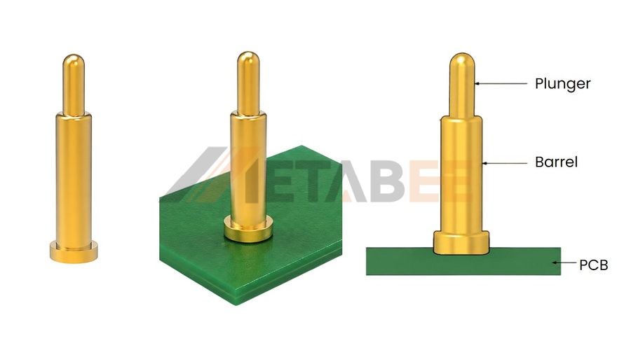
Surface mount pogo pins, also known as SMT or SMD pogo pins, are designed to be mounted directly onto the surface of a PCB without requiring through-holes. Their compact termination makes them well suited to space-constrained PCB layouts and automated assembly processes.
SMT pogo pins can be soldered directly to designated PCB pads, providing a stable electrical connection while allowing the plunger to move vertically during mating. Their surface-mount design also makes them convenient for high-volume electronic manufacturing where consistent PCB assembly is important.
Typical applications include:
l Wearable devices
l Charging docks
l Consumer electronics
l Compact electronic modules
Through-Hole (THT) Pogo Pins
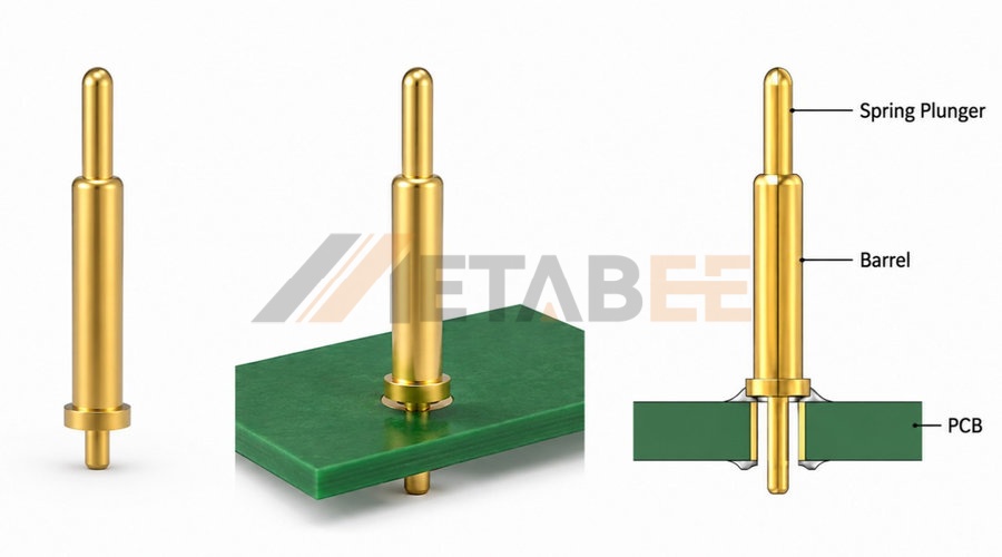
Through-hole pogo pins are designed to be inserted through holes in a PCB and secured by soldering. Compared with surface-mount versions, this termination method provides strong mechanical retention and can be useful when the pogo pin may experience greater mechanical stress during operation.
The through-hole structure is also suitable for PCB designs where the available board layout supports drilled mounting holes. These pogo pins are commonly selected when mechanical stability is an important consideration alongside reliable electrical contact.
Typical applications include:
l Industrial equipment
l Test and measurement equipment
l PCB assemblies
l Electronic devices requiring secure PCB mounting
Right Angle Pogo Pins
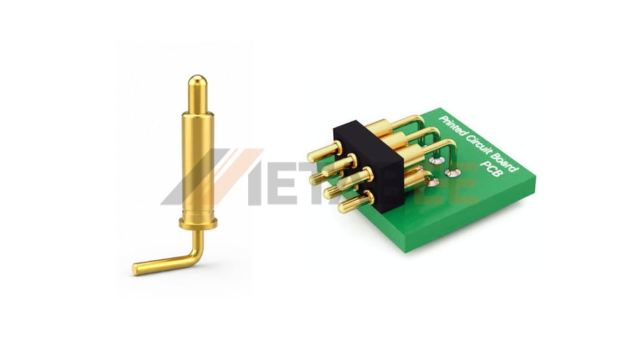
Right-angle pogo pins are designed so that the contact direction is positioned approximately 90 degrees relative to the mounting surface. This configuration allows electrical contact to be made from the side rather than directly from above.
By changing the contact orientation, right-angle pogo pins can help engineers work around height restrictions or accommodate mating components positioned perpendicular to the PCB. They are particularly useful when the mechanical layout does not allow a conventional vertical pogo pin to be used.
Typical applications include:
l Compact electronic assemblies
l Side-facing electrical contacts
l Space-constrained PCB designs
l Devices with perpendicular mating surfaces
Solder Cup Pogo Pins
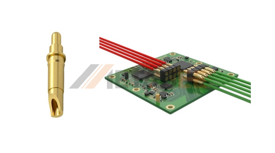
Solder cup pogo pins feature a solder cup termination that allows a wire or cable to be attached directly to the contact. This configuration provides flexibility when integrating a spring-loaded contact into a wired electronic assembly.
The solder cup provides a dedicated termination area for the conductor, while the pogo pin mechanism maintains the required contact force at the mating end. Electrical performance can be affected by factors such as contact resistance, contact force, conductive materials, and plating.
Solder cup pogo pins are useful for assemblies where a wire-connected spring-loaded contact is required.
Typical applications include:
l Wire-to-board connections
l Battery connections
l Test equipment
l Custom electronic assemblies
Double-Ended Pogo Pins
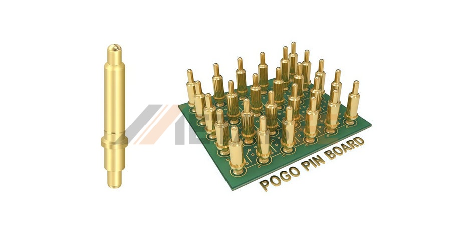
Double-ended pogo pins feature spring-loaded contact points at both ends of the component. Each end can engage with a corresponding conductive mating surface, allowing electrical connectivity through the two contact points.
The design provides spring-loaded movement on both ends, with each contact point contributing to the overall mechanical and electrical connection. Important performance parameters include contact force, working stroke, contact resistance, alignment, and mating cycles.
Double-ended pogo pins are suitable for compact assemblies where electrical contact is required between two opposing components or conductive surfaces.
Typical applications include:
l Board-to-board connections
l Module-to-module connections
l Battery and electronic modules
l Test fixtures
How to Choose the Right Pogo Pin
Choosing the right pogo pin starts with identifying the specific connection requirements of the application. Mounting method, contact orientation, termination style, and contact configuration can help determine the appropriate pogo pin type, while factors such as contact force, working stroke, dimensions, and electrical requirements can then be used to select the right specification.
|
Key Features |
What to consider |
Pogo Pin type to consider |
|
Mounting Type |
Match the termination with the PCB or connection method |
SMT/SMD, THT, Solder Cup |
|
Pitch |
Check the spacing between adjacent contacts, especially in compact multi-contact layouts |
SMT/SMD / THT, depending on the PCB design |
|
Installation Space |
Consider the available height, footprint, and contact direction |
SMT/SMD or Right-Angle |
|
Contact Configuration |
Consider whether electrical contact is required at one or both ends |
Double-Ended when both ends need to provide contact |
|
Contact Force |
Select the force required to maintain stable contact during compression |
Product-specific |
|
Working Stroke |
Ensure sufficient plunger travel for the required compression |
Product-specific |
|
Current Rating |
Verify that the rated current meets the application's electrical load |
Product-specific |
|
Contact Resistance |
Consider the maximum acceptable resistance for the connection |
Product-specific |
|
Material & Plating |
Consider conductivity, corrosion resistance, and wear requirements |
Product-specific |
|
Insulation Resistance |
Check when electrical isolation between contacts is required |
Product-specific |
|
Mating Cycles |
Consider the expected frequency of connection and disconnection |
Product-specific |
After determining the required configuration, product-specific specifications such as pitch, contact force, working stroke, dimensions, current rating, contact resistance, material, plating, and mating cycles should be checked to identify the appropriate pogo pin.
Not sure which pogo pin type is right for your device? Reach out to Metabee's engineering team today for expert guidance and custom solutions tailored to your exact needs.
Application
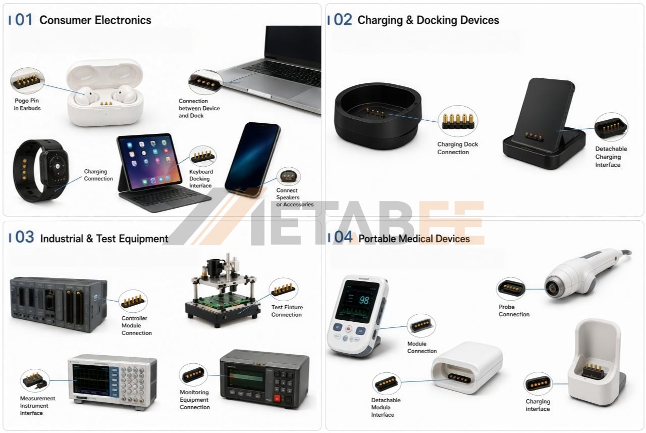
Pogo pins are used across a variety of electronic products and equipment where compact, reliable, and repeatable electrical connections are required. Common applications include consumer electronics, charging and docking devices, industrial and test equipment, and portable medical devices.
Consumer Electronics
Pogo pins are widely used in laptops, tablets, earbuds, headphones, smartwatches, and other portable electronic devices. Their compact structure makes them suitable for applications where space is limited, while the spring-loaded contact helps maintain a stable electrical connection between mating surfaces.
Charging & Docking Devices
Charging docks, charging cases, docking stations, and other detachable charging accessories commonly use pogo pins to establish electrical contact between the device and its charging interface. Their spring-loaded mechanism allows the contacts to accommodate small variations in alignment while supporting repeated connection and disconnection.
Industrial & Test Equipment
Pogo pins can be used in industrial controllers, automation equipment, monitoring instruments, test fixtures, and measurement equipment that require reliable electrical contact. Depending on the equipment design, they can provide convenient connections for PCB assemblies, modules, or test interfaces, particularly where repeated mating or compact contact points are required.
Portable Medical Devices
Portable medical and diagnostic devices can use pogo pins for compact internal connections, detachable modules, and charging interfaces. Their small size and spring-loaded contact make them suitable for electronic equipment where installation space is limited and reliable, repeatable connections are required.
Conclusion
In summary, pogo pins provide a highly reliable, space-efficient solution for maintaining stable electrical connections in modern electronic devices. By utilizing a simple yet effective spring-loaded mechanism—comprising a plunger, spring, and barrel—they ensure consistent contact force and seamless electrical continuity. However, as highlighted in this guide, choosing the wrong configuration can easily lead to poor connectivity, mechanical failure, and costly redesigns.
To guarantee optimal performance, it is crucial to select the correct pogo pin type—whether that is an SMT, through-hole, right-angle, solder cup, or double-ended design—based on your specific PCB layout, mounting method, and available space. By carefully evaluating key specifications like contact force and working stroke, you can secure the perfect connection for your project. If you are looking for precision-engineered, spring-loaded solutions tailored to your exact mechanical and electrical requirements, Metabee offers a comprehensive range of high-quality pogo pins to bring your innovative designs to life. Contact us today to discover our premium pogo pins and experience exceptional customer support.
Related Products:
Pogo Pin Spring Loaded Contacts
Pogo Pin Single Pin Series
Single Row/Double Row Male and Female Connector
Pogo Pin Multi-pin Connector Series
FAQ
Q: How many mating cycles can a pogo pin withstand?
A: Pogo pins are incredibly durable. Standard pogo pins typically endure anywhere from 10,000 to 100,000 mating cycles. Specialized high-performance pins, often used in automated test equipment (ATE), can even exceed 1,000,000 cycles, outlasting conventional connectors significantly.
Q: Are pogo pins waterproof?
A: Standard pogo pins are not naturally waterproof. However, manufacturers offer specialized waterproof pogo pins (often rated IP67 or IP68) that use O-rings, silicone seals, or insert-molding techniques to prevent water and dust ingress, making them ideal for smartwatches, outdoor equipment, and medical devices.
Q: How much current can a standard pogo pin carry?
A: A standard pogo pin is usually rated for 1A to 2A, which is sufficient for signal transmission and standard charging. For fast-charging applications or power-hungry devices, you can opt for high-current pogo pins that feature customized internal structures (like ball contacts) to safely handle 5A, 10A, or even up to 30A+.
Q: Can pogo pins go through a standard reflow soldering process?
A: Yes. Surface-mount (SMT/SMD) pogo pins are specifically designed to withstand the high temperatures of standard reflow soldering. They are compatible with automated pick-and-place assembly lines, ensuring efficient mass production.
Q: What happens if a pogo pin is over-compressed?
A: Every pogo pin has a recommended "working stroke" and a "maximum stroke." If a pin is compressed beyond its maximum stroke (bottoming out), it can permanently deform or damage the internal spring. This leads to a loss of restoring force and ultimately causes a poor electrical connection.
Q: Can pogo pins transmit high-frequency data signals?
A: Yes, but specialized designs are required. While standard pogo pins are excellent for power and low-speed data, custom impedance-matched pogo pins (often arranged in coaxial configurations) can be engineered to transmit high-speed RF, USB, or antenna signals with minimal interference.
Q: Can I customize pogo pins for my specific project?
A: Absolutely. If off-the-shelf options don't fit your exact mechanical or electrical constraints, you can customize the pin's height, travel distance, contact force, plating material, and current capacity. Metabee specializes in OEM/ODM services and can help you engineer the perfect custom pogo pin solution for your device. Need a custom spring-loaded connector? Welcome to contact Metabee—our experts are ready to design, manufacture, and deliver the ideal pogo pin for your unique application.
