
While wireless technology continues to evolve, the backbone of modern digital infrastructure remains the hardwired Ethernet connection. At the heart of this reliability is the RJ45 connector. For networking professionals and hardware buyers, understanding the technical nuances—from wiring standards to shielding—is essential to prevent signal loss and ensure network integrity. This guide provides a comprehensive analysis of RJ45 technology to help you make informed decisions for your networking environment.
Definition
An RJ45 connector is a standardized 8P8C (8-Position, 8-Contact) modular interface used to terminate twisted-pair Ethernet cables for high-speed data networking and telecommunications. The term "RJ45" is among the most widely recognized in the IT and telecommunications sectors, yet it is frequently misunderstood. "RJ" stands for "Registered Jack," a standardized telecommunication network interface designated by the Federal Communications Commission (FCC) in the United States. Originally, the RJ45 standard was developed for telephone routing and utilized a keyed configuration.
However, the connector we universally refer to as "RJ45" in modern Ethernet networking is technically an 8P8C (8-Position, 8-Contact) modular connector. Over time, the industry colloquially adopted the RJ45 nomenclature for these 8P8C connectors used for computer networking. Therefore, when sourcing RJ45 8p8c connectors today—such as the reliable solutions offered by Metabee—you are purchasing the standard modular interface used for twisted-pair Ethernet cables (like Cat5e, Cat6, and Cat6a).
These connectors are designed to terminate twisted-pair cables and interface with female sockets on devices like switches, routers, servers, and computers. To ensure universal compatibility across different hardware manufacturers globally, standard RJ45 connector dimensions are strictly regulated. The typical plug is approximately 11.69 mm wide and 6.60 mm high, ensuring a snug, standardized fit in any standard female jack and maintaining optimal contact pressure and signal integrity across millions of devices worldwide.
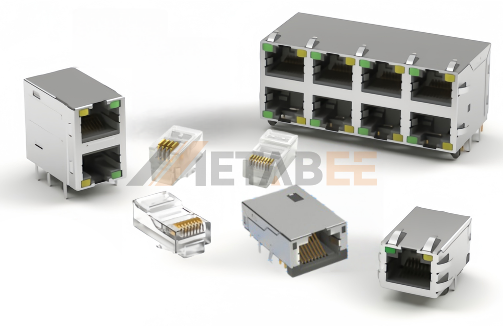
RJ45 Connector Components
An Ethernet connection consists of two mating parts: the Plug (Male) and the Jack (Female). Understanding the internal components of both is essential for a reliable link.
Components of the RJ45 plug connector
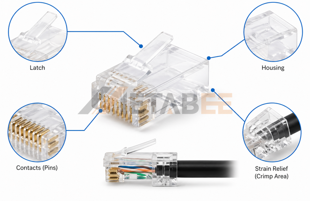
While it may appear to be a simple piece of plastic, it consists of several vital parts designed for mechanical stability:
- Housing (Plastic Body): The main body is typically manufactured from clear, high-impact polycarbonate. For enterprise and industrial applications, this housing must often meet specific flammability standards, such as UL 94V-0 or 94V-2. The transparency is functional, allowing technicians to visually verify the RJ45 connector wire order before the irreversible crimping process.
- Contacts (Pins): These are the metallic elements inside the connector that bite into the copper wires of the Ethernet cable and make physical contact with the pins inside the jack. They are usually made of phosphor bronze and are plated with a layer of nickel followed by a layer of gold. The gold plating is crucial for preventing oxidation in humid environments and ensuring low electrical resistance over decades of use.
- The Latch (Retention Tab): A flexible plastic clip on the top (or bottom) of the connector. It clicks into place when inserted into a port, ensuring the plug is not accidentally dislodged by cable tension, gravity, or vibrations in server racks.
- Strain Relief (Crimp Area): Located at the rear of the connector, this area is compressed during the termination process. It bites down on the cable's outer jacket, transferring pulling tension away from the fragile internal copper conductors.
Components of the RJ45 jack connector
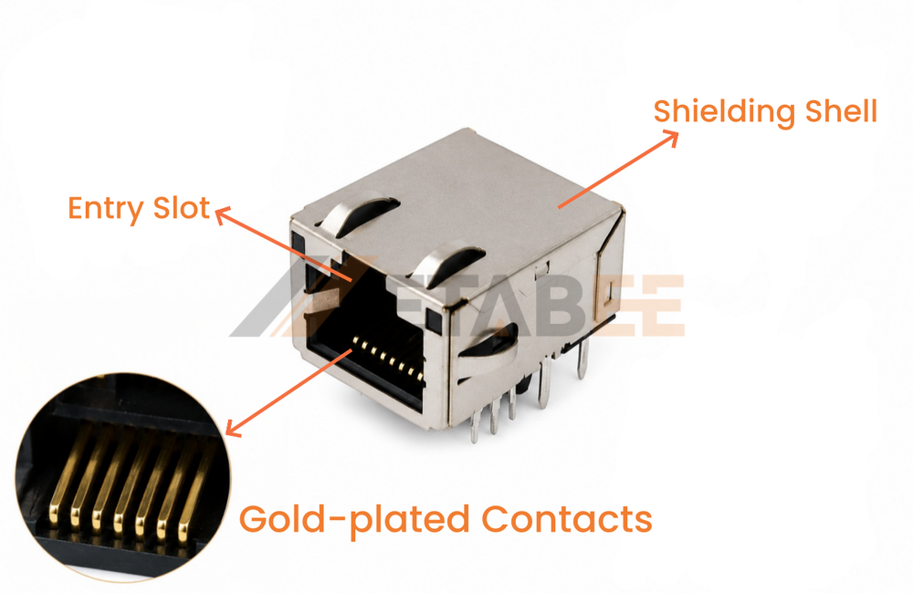
The RJ45 jack connector is a standard interface designed for reliable data transmission. Its primary components include:
- Entry Slot & Locking Mechanism: The physical aperture for the 8P8C modular plug, integrated with a precision-engineered retention feature. This mechanism provides a secure "click" upon insertion and ensures high retention strength, preventing accidental disconnection due to vibration or tension—a critical requirement for industrial automation and reliable network performance.
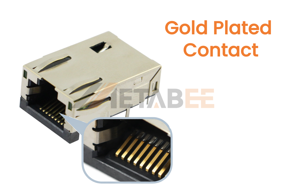
- Gold-plated Contacts: Spring-loaded pins that ensure a low-resistance electrical path. Gold plating (typically 3µ" to 50µ") prevents oxidation and ensures long-term durability. Plating thickness is a configurable variable, selected based on the expected mating cycles and environmental conditions.
- Housing (Shielding Options): The external structure supporting the internal components, available in two primary configurations:
Unshielded: Uses a standard plastic housing, providing a cost-effective solution for general, low-noise environments.
Shielded: The housing is encased in a conductive metal shell for grounding and EMI/RFI protection.
RJ45 Color Code and Pinout
Understanding the wiring standards is the most critical aspect of creating a functional Ethernet cable. Even a minor deviation in the sequence can lead to packet loss, reduced speeds, or a completely dead link.
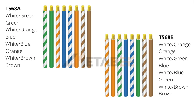
T568A vs. T568B: The Color Coding Standards
The telecommunications industry, via the TIA/EIA, established two primary color-coding standards to ensure that data signals are sent and received correctly across twisted-pair cables. These standards define which colored wire belongs to which specific pin.
- T568A Color Code: This standard was originally designed for backward compatibility with older telephone systems (USOC). It is often found in residential installations and government projects. The primary characteristic of T568A is that the Green pair is assigned to pins 1 & 2, while the Orange pair is assigned to pins 3 & 6.
- T568B Color Code: This is the most common color coding standard used in commercial networking today. In this configuration, the Orange pair is moved to pins 1 & 2, and the Green pair is moved to pins 3 & 6.
- Why Color Matters: The internal twists of each color pair (Orange, Green, Blue, Brown) are calculated at different rates by manufacturers to minimize interference. Swapping the color groups incorrectly can lead to signal "bleeding" between pairs, even if the electrical continuity is maintained.
RJ45 Pinout: Signal Assignments (TX/RX)
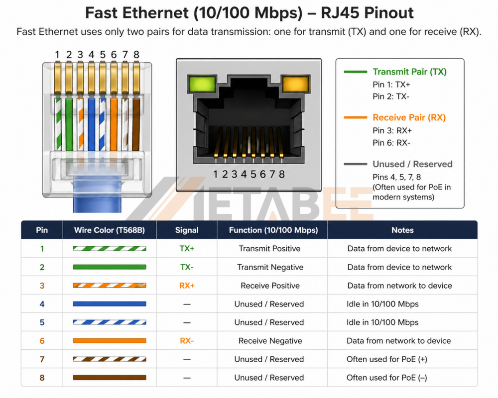
The rj45 connector pin details define the electrical path for data transmission. While all 8 pins are physically present, their logical roles vary depending on the network speed:
Fast Ethernet (10/100 Mbps):
- Pin 1 & 2: Transmit Pair (TX+ / TX-). These pins carry data from the device to the network.
- Pin 3 & 6: Receive Pair (RX+ / RX-). These pins receive data from the network.
- Pins 4, 5, 7, and 8: Reserved/Unused. In older systems, these pins are idle, though they are often used for Power over Ethernet (PoE) in modern setups.
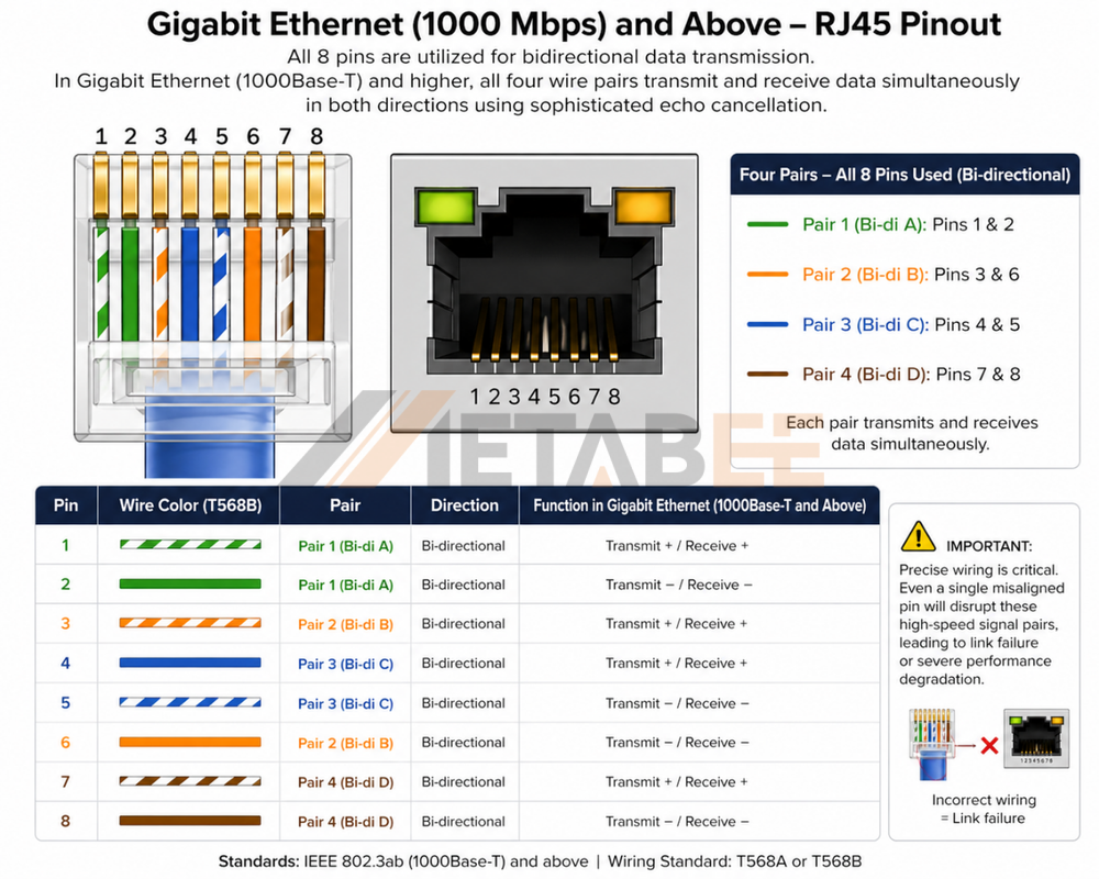
Gigabit Ethernet (1000 Mbps) and Above:
All 8 Pins (1-8): Utilized for bidirectional data. In Gigabit technology (1000Base-T), each of the four wire pairs transmits and receives data simultaneously in both directions using sophisticated echo cancellation.
- Pair 1: Pins 1 & 2 (Bi-di A)
- Pair 2: Pins 3 & 6 (Bi-di B)
- Pair 3: Pins 4 & 5 (Bi-di C)
- Pair 4: Pins 7 & 8 (Bi-di D)
Ensuring the precision of the wiring diagram rj45 connector is vital; even a single misaligned pin will disrupt these complex signal pairs, leading to link failure or severe performance degradation.
RJ45 Connector Color Code Comparison Table
To wire a connector correctly, hold the RJ45 plug with the copper contacts facing UP and the cable entry pointing toward you. Pin 1 is on the far left. The table below compares the wire order for the T568A and T568B standards:
|
Pin Number |
T568A Wire Color (Alternative) |
T568B Wire Color (Standard) |
Signal (10/100 Mbps) |
|
1 |
White/Green |
White/Orange |
Transmit (TX+) |
|
2 |
Green |
Orange |
Transmit (TX-) |
|
3 |
White/Orange |
White/Green |
Receive (RX+) |
|
4 |
Blue |
Blue |
Reserved / PoE |
|
5 |
White/Blue |
White/Blue |
Reserved / PoE |
|
6 |
Orange |
Green |
Receive (RX-) |
|
7 |
White/Brown |
White/Brown |
Reserved / PoE |
|
8 |
Brown |
Brown |
Reserved / PoE |
Note: As shown in the table, T568A and T568B only differ by swapping the Green and Orange pairs (Pins 1 & 2 swapped with Pins 3&6).
Types of RJ45 Connectors
As networking environments diversify from data centers to industrial floors, hardware must adapt in both form and function. This evolution has created specialized connector types designed to meet specific mechanical, electrical, and environmental demands.
Plug & Jack
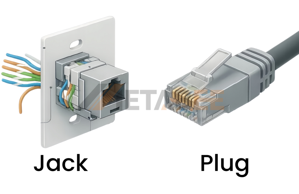
RJ45 Plug Connector: The male termination found on patch cables. It is designed for mobility and frequent insertion.
RJ45 Jack Connector: The female interface. In professional settings, these are often "Keystone" jacks, which snap into wall plates or patch panels. High-quality jacks feature "IDCs" (Insulation Displacement Connectors) on the back, where wires are punched down using a specialized tool.
Crimping Type
- Standard (Closed-end) Plug: The traditional type where wires are cut to a precise length and pushed into the plug until they hit the "back wall." It requires careful measurement to ensure the cable jacket is secured under the strain relief.
- Pass-Through (EZ) Plug: These plugs have open holes at the tip. Wires are pushed all the way through the connector, making it easy to verify the color order before crimping. A specialized tool then crimps the plug and trims the excess wire simultaneously.
- Two-Piece (with Load Bar): Common for Cat6/6a cables. Wires are first arranged into a small plastic "load bar," which is then slid into the main housing. This maintains the wire twists closer to the contacts for better signal performance.
- Field Termination Plug (Toolless): A robust, usually shielded plug designed for high-speed Cat6a/Cat8 links. It uses IDC blocks inside and can be closed by hand or with simple pliers, making it ideal for industrial environments.
Mounting Type
In the electronics manufacturing industry, how an RJ45 jack is mounted to the Printed Circuit Board (PCB) is a critical technical specification that defines the product's durability and production efficiency. There are two primary professional mounting technologies used:
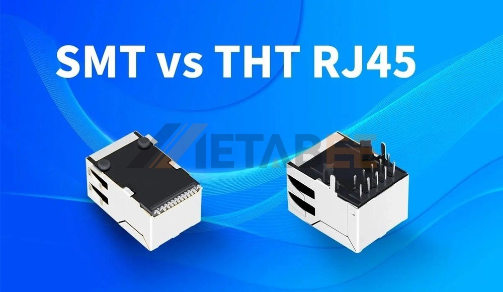
- Surface Mount Technology (SMT): SMT RJ45 connectors are designed to be soldered directly onto the surface of the PCB. This is the preferred choice for modern, high-density, automated production lines. SMT components allow for smaller device footprints and enable the use of both sides of the PCB.
- Through-Hole Technology (THT): THT connectors feature metallic leads that pass through pre-drilled holes in the PCB and are soldered on the underside. This provides the highest level of mechanical durability and "peel-off" resistance.
Cable Category
The internal architecture of the connector must match the performance category of the cable to maintain bandwidth integrity. Below is a comparison table showing the diversity of shielding options and technical parameters for common cable categories:
|
Category |
Max Speed |
Max Bandwidth |
Max Distance |
Common Shielding Types |
Typical Application |
|
Cat5e |
1 Gbps |
100 MHz |
100 Meters |
U/UTP (Unshielded), F/UTP |
Residential and Basic Office |
|
Cat6 |
10 Gbps* |
250 MHz |
55 Meters* |
U/UTP, F/UTP, U/FTP |
Commercial and High-Speed LAN |
|
Cat6a |
10 Gbps |
500 MHz |
100 Meters |
U/UTP, F/UTP, S/FTP |
Data Centers and Enterprise |
|
Cat7 |
10 Gbps |
600 MHz |
100 Meters |
S/FTP, F/FTP |
Industrial and Specialized AV |
|
Cat8 |
40 Gbps |
2000 MHz |
30 Meters |
S/FTP, F/FTP |
Switch-to-Switch (Data Centers) |
*Cat6 supports 10 Gbps up to 37-55 meters depending on crosstalk conditions. Most industrial Cat6a/7/8 applications require shielding to mitigate Alien Crosstalk (AXT) at high frequencies.
Technical Characteristics:
To ensure the best performance, the RJ45 connector's internal design evolves alongside these categories:
- Cat5e Connectors: The most basic design. Since frequencies are low (100MHz), wires are usually kept in a straight horizontal line inside the plug.
- Cat6 Connectors: Because Cat6 wires are thicker (usually 23 AWG) and more tightly twisted, an rj45 connector cat6 often utilizes a "three-prong" contact and a staggered internal loading bar (zig-zag arrangement) to reduce crosstalk.
- Cat6a and Cat7 Connectors: These require specialized metal-housed (shielded) connectors to handle the 500MHz+ frequencies and provide a grounding path.
- Cat8 Connectors: Designed for extreme 2000MHz frequencies, Cat8 connectors often move away from traditional "crimp-on" styles toward field-termination designs with internal compensation circuitry.
Shielded vs. Unshielded
Choosing between rj45 connector shielded vs unshielded is the most significant technical decision in network infrastructure planning. This choice determines the network's resilience against external "noise" and its long-term stability.
Shielded Types
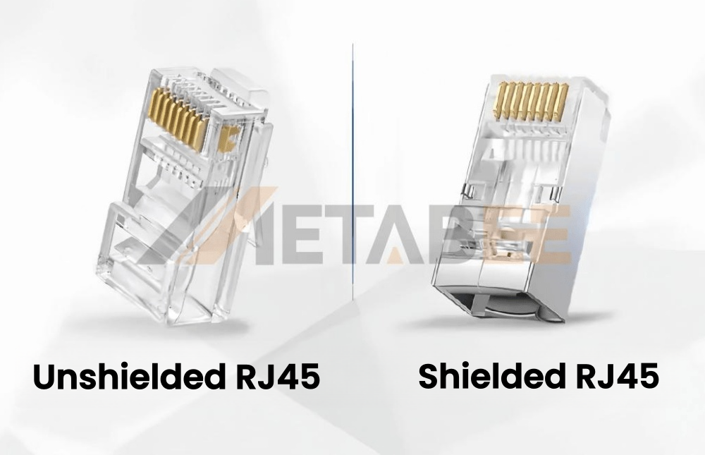
Shielded RJ45 connectors feature a metallic "shroud" or shell (typically nickel-plated brass or zinc alloy) that acts as a Faraday cage to block external interference.
- STP (Shielded Twisted Pair): A general umbrella term for any cable/connector with a shielding structure. It refers to an RJ45 with a metal shell designed to terminate shielded cables, providing fundamental protection against EMI and serving as the baseline for high-interference environments.
- S/FTP (Braid over Foiled Twisted Pair): Consists of an overall metal braid shield combined with individual foil shields for each pair. It focuses on mechanical strength and full-spectrum protection; the braid provides superior grounding continuity and physical durability for low-frequency shielding, while the foil handles high-frequency noise, making it the standard for Cat7 and Cat8.
- SF/UTP (Braid & Foil over Unshielded Twisted Pair): Features both a braid and a foil overall shield wrapping around unshielded pairs. It focuses on maximum external EMI protection, providing two layers of defense against heavy external noise in environments where individual pair shielding is not required.
Unshielded Type
U/UTP (Unshielded Twisted Pair): The most ubiquitous networking interface worldwide, featuring no shielding layers. It focuses on flexibility and simplicity, relying on the principle of "Differential Signaling" and precise wire twisting to cancel out noise, which is significantly more cost-effective and does not require complex grounding infrastructure.
Advantages & Disadvantages of RJ45 Connectors
To understand why the RJ45 has remained the industry standard for decades, we must weigh its undeniable strengths against its inherent physical limitations.
Advantages
- Universal Interoperability: The 8P8C standard is truly global. A patch cable manufactured in one region will seamlessly interface with networking hardware produced anywhere else, ensuring a standardized and highly reliable supply chain.
- Efficient Power Delivery (PoE): When combined with high-specification hardware, it can deliver both data and electricity (up to 90W) over a single cable. It is important to note that this capability is not universal; it requires connectors that meet advanced standards (like PoE++ / 802.3bt) and feature 50-micron gold plating with high-gauge (AWG) internal wiring to safely manage the heat generated by higher power levels.
- Low Maintenance & High Durability: Once properly terminated, it can remain active for decades. Unlike wireless signals that can be disrupted by physical obstacles or interference, a hardwired RJ45 connection offers unmatched stability.
- Backward Compatibility: Cat6a connectors are physically compatible with older Cat5 jacks. This allows businesses to upgrade their network infrastructure in phases without the need to replace every switch and patch panel at once.
Disadvantages
- Mechanical Fragility (The Latch): The flexible plastic retention tab is the most common point of failure. Once the tab breaks, the connector easily slips out of the port, leading to frustrating and intermittent connection drops.
- Signal Crosstalk at High Speeds: Close physical proximity of the 8 pins becomes a technical bottleneck at 40Gbps. Preventing signals from "bleeding" between these tightly packed pins requires increasingly complex and expensive internal shielding designs.
- Termination Complexity: High-category cables require specialized tools and practice. Unlike simpler telephone wires, terminating a heavily shielded Cat6a or Cat8 cable demands precision to maintain the internal wire twists and grounding paths.
- Distance Limitations: Limited to 100 meters (328 feet) for copper. Beyond this strict limit, signal attenuation requires active repeaters, network switches, or a transition to fiber optic cables.
How to Choose the Right RJ45 Connector
Selecting the right connector involves four logical steps to ensure performance and longevity. Misalignment between connector specs and cable types leads to poor electrical contact.
Step 1: Match Contacts to Conductors
Check your cable jacket for "Solid" or "Stranded" markings to choose the correct internal prongs.
Solid Cable (In-Wall): Requires 3-Prong Contacts to safely "straddle" the stiff copper core without breaking it.
Stranded Cable (Patch Cords): Requires 2-Prong Contacts to pierce into the flexible wire bundle.
Step 2: Select the Installation Style
Standard (Closed End): Wires must be pre-trimmed. Professional, but prone to ordering mistakes.
Pass-Through (EZ Style): Wires push through the front, allowing visual color verification before crimping. Highly recommended for reducing errors.
Field Termination: Tool-less, heavy-duty connectors ideal for Cat6a/7/8 deployments.
Step 3: Determine Plating Grade (Gold over Nickel)
High-quality contacts use a base layer of Nickel to prevent copper migration, topped with Gold to resist corrosion.
Flash Gold: Very thin (<3u"). For temporary or budget consumer use only.
Intermediate (15u" - 30u"): Cost-effective for standard office environments.
50 Micron (50u"): The industrial gold standard. Required for PoE, data centers, and long-term durability (>750 mating cycles).
Step 4: Shielding Requirements
UTP (Unshielded): Best for standard office or home networks.
STP/FTP (Shielded): Mandatory if running cables near high-voltage lines or in dense server racks to prevent EMI. Ensure the metal shell is properly grounded.
Conclusion
The RJ45 8P8C connector remains the indispensable foundation of global wired networking, serving as the critical bridge between complex infrastructure and end-user devices. By standardizing the physical interface and wiring protocols—specifically through the T568A and T568B color codes—the industry has ensured a level of universal interoperability that allows for seamless communication across diverse hardware platforms. Understanding the interplay between pinout logic, signal integrity, and the physical components of the connector is not merely a technical requirement but a necessity for building stable, high-speed digital environments.
As network demands push toward higher bandwidths like 10Gbps and beyond, the choice of the correct RJ45 connector becomes increasingly strategic. Selecting the appropriate category, shielding type, and gold-plating thickness is essential to prevent performance bottlenecks and ensure long-term mechanical durability. Whether deploying a simple home network or a mission-critical data center, choosing high-quality components from reliable brands like Metabee, combined with precise termination practices, will guarantee a resilient and efficient connection that can withstand the evolving challenges of modern telecommunications.
Ready to Source High-Quality RJ45 Connectors?
At Metabee, we are dedicated to designing and manufacturing high-precision RJ45 interconnect solutions that meet the most demanding industry standards. Whether you are looking for a customized magnetic module for a unique chipset or a reliable, mass-produced jack for large-scale deployments, our experienced engineering team is ready to help you optimize your connectivity.
Contact us today to request a formal quote, receive free product samples, or schedule a technical consultation for your next PCB design project. Let Metabee be your trusted partner in building the next generation of networking infrastructure.
Related Products:
FAQ
Q1: Can I use a Cat6 RJ45 connector on a Cat5e cable, or vice versa?
A: Yes, they are physically compatible, but it is not recommended for optimal performance. Using a Cat6 connector on Cat5e cable is fine, but using a Cat5e connector on Cat6 cable will create a "bottleneck," limiting your speed to Cat5e standards and potentially causing signal loss due to the thinner internal components of the Cat5e plug.
Q2: What is the difference between T568A and T568B, and which one should I use?
A: The only difference is the color position of the green and orange wire pairs. While both work identically, T568B is the dominant standard in modern commercial networking. You should use T568B for most projects unless you are working on a government contract or a legacy residential system that already uses T568A.
Q3: Does a "Pass-Through" RJ45 connector affect the internet speed?
A: No, when crimped correctly, pass-through connectors provide the same speed as standard ones. The main advantage is that the wires slide through the front, making it much easier to verify the color order and ensuring the cable jacket is fully seated inside the plug for better strain relief.
Q4: Is a shielded (STP) RJ45 connector always better than an unshielded (UTP) one?
A: Not necessarily; unshielded is often better for home use. Shielded connectors only provide a benefit if you have a grounded system and are dealing with high Electro-Magnetic Interference (EMI). If you use shielded connectors without proper grounding, they can actually act as an antenna and attract more interference, degrading your signal.
Q5: Why do some RJ45 connectors have 50-micron gold plating while others have "flash" gold?
A: Gold plating thickness determines the durability and longevity of the connection. 50-micron (50u") gold plating is the industrial standard because it resists corrosion and can handle hundreds of plug/unplug cycles. "Flash" gold is very thin and will wear off quickly, leading to oxidation and poor connection over time.
Q6: Can all RJ45 connectors handle Power over Ethernet (PoE)?
A: While most can, high-power PoE++ requires high-quality connectors. For modern devices like security cameras or high-end Wi-Fi APs that use 60W or 90W of power, you should use 50-micron gold-plated connectors with 3-prong contacts to prevent overheating and ensure stable power delivery.
Q7: Why does the plastic clip (latch) on my RJ45 connector break so easily?
A: This is a common design flaw, but choosing "snagless" boots can prevent it. The clip is thin plastic, designed to be flexible. To avoid breaking it, you should use connectors with protective "boots" that cover the latch, preventing it from getting caught on other cables when you pull them through a bundle.
