
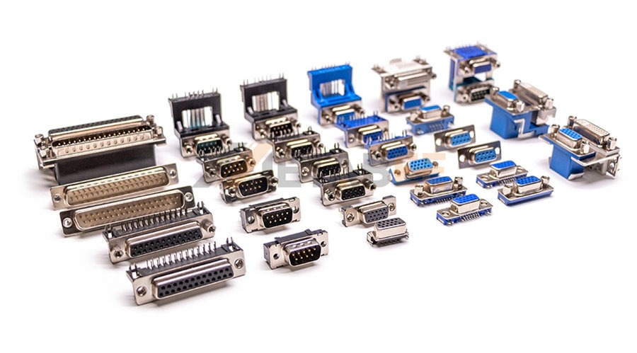
The D-subminiature, or D-sub connector, is perhaps one of the most recognizable and enduring components in industrial and electronic connectivity. Its distinctive D-shaped metal shell ensures correct polarization and provides essential shielding. These features have cemented the D-sub's status as a reliable interface solution for decades. It was universally used in early computer serial ports (RS-232). Today, the D-sub remains a cornerstone of system design, proving its continued necessity in modern aerospace, medical devices, and heavy industrial machinery.
Related Post: What is D-Sub? A Comprehensive Guide to D-Sub Connectors
Yet, despite its seemingly simple appearance, the term "D-sub connector" covers a vast array of technical specifications, variations, and specialized configurations. Selecting the correct component requires moving beyond the basic 9-pin or 25-pin models and understanding the full taxonomy.
Our mission in this guide is to provide a definitive technical breakdown. We will explore the primary ways D-sub connector types are categorized. Specifically, we will examine physical size and pin density, as well as advanced termination styles. We will also cover specialized environmental performance features. By the end, you’ll be equipped with the knowledge needed to specify the ideal D-sub solution for your most demanding applications.
Classification 1: By Shell Size, Pin Density, and Combination Types
The first and most fundamental way to categorize D-sub connectors is based on their physical shell size and the density of contacts they contain. This classification determines the overall mechanical footprint of the connector.
Standard Density D-Sub Connectors (5 Types)
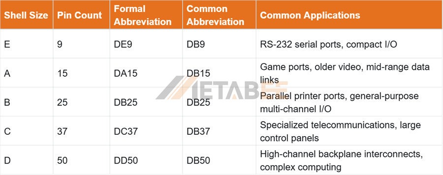
Standard density D-sub connectors are the foundational types, placing contacts in 2 staggered rows within their metal shells. A key common parameter across these types is the standard 2.77mm (0.109 inch) contact pitch. The letter in the naming convention (E, A, B, C, D) refers to the shell size, while the number indicates the contact count.
The table below lists the shell size, pin count, name, and application for standard D-sub connectors.
Brief Introductions to 5 Standard D-Sub Types:
DE9 or DB9 Connectors (E-size, 9 contacts)
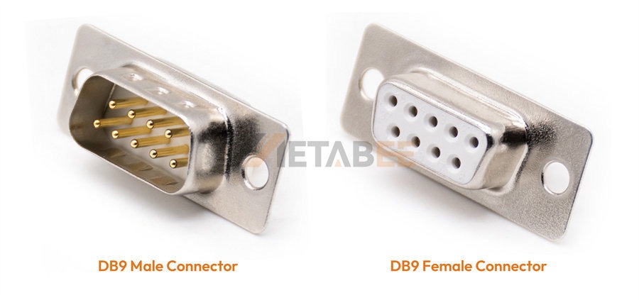
The DB9 connector is the smallest and most recognized D-sub connector, historically synonymous with the RS-232 serial standard. It remains common in industrial automation and specialized control systems.
Related Posts:
DA15 or DB15 Connectors (A-size, 15 contacts)
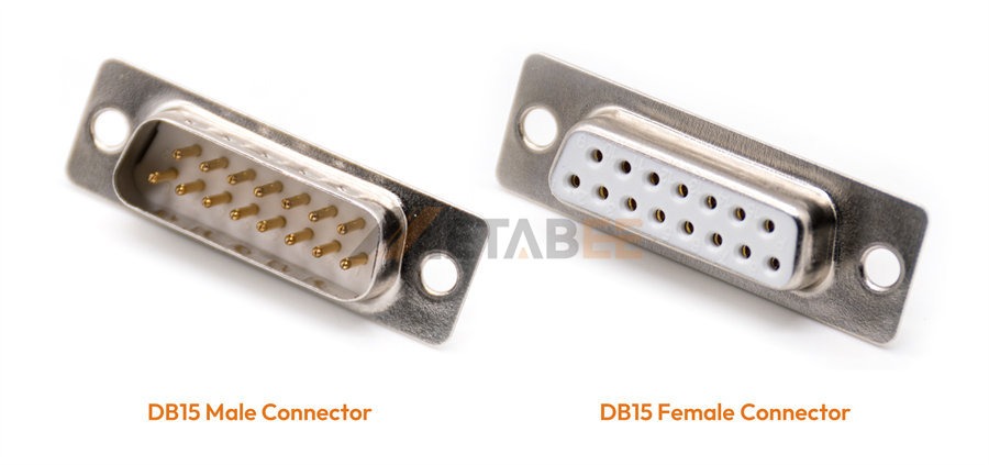
Utilizing the next size up from the E-shell, the DB15 connector was used for PC game ports and older video applications. It is now frequently employed in military and aerospace systems for specialized data links where nine contacts are insufficient.
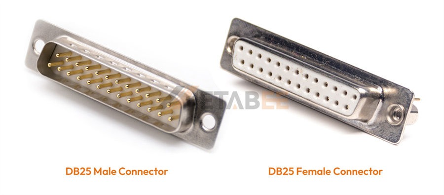
DB25 Connectors (B-size, 25 contacts)
This medium-sized D-sub connector is famously associated with the Parallel Printer Port. In modern industrial settings, the DB25 connector is a workhorse for general-purpose, multi-channel I/O, valued for its balanced size and signal capacity in test equipment and controllers.
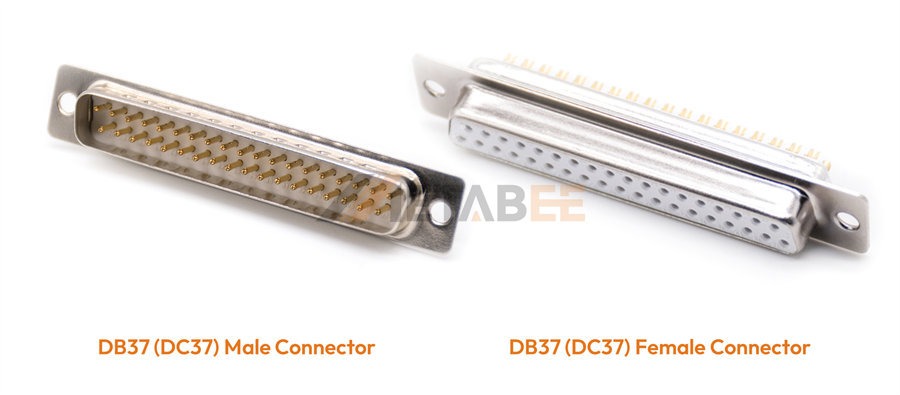
DC37 or DB37 Connectors (C-size, 37 contacts)
A larger chassis interface offering a significant number of signal paths. The DB37 connector is commonly specified in specialized telecommunications equipment and larger control panels where signal density is required without moving to a high-density contact arrangement.
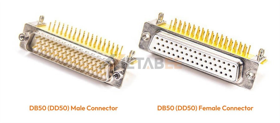
DD50 or DB50 Connectors (D-size, 50 contacts)
The largest of the five common standard D-subs, the DB50 connector provides the highest channel count in a standard density configuration. It is utilized in high-channel count backplane interconnects, complex computing systems, and defense applications. These demanding roles require the connector to provide both high capacity and extreme ruggedization.
High-Density D-Sub Connectors (6 Types)
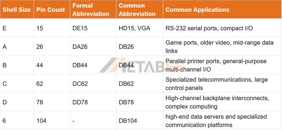
High-density D-Sub connectors are frequently referred to as 'HD' connectors. They utilize the same physical shell sizes as the standard D-sub types. However, they dramatically increase the contact count by arranging them in 3-5 staggered rows instead of two. A key differentiator for these connectors is their reduced contact pitch of 2.29mm (0.090 inch). This innovation is crucial for achieving high signal transmission capacity in a constrained space.
The table below lists the shell sizes, pin counts, standard names, and common applications for High Density D-sub connectors.
Brief Introductions to High-Density D-Sub Types
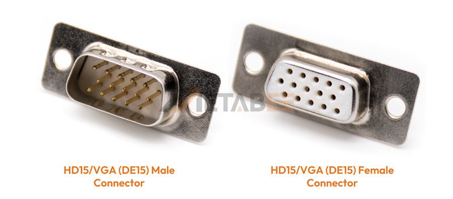
DE15, HD15 or VGA Connectors (E-size shell, 15 contacts)
HD15 connectors are the standard connectors for VGA and SVGA analog video. It achieves 15 contacts in the smallest E shell size by using the triple-row arrangement, necessary for separate color channels and synchronization lines.
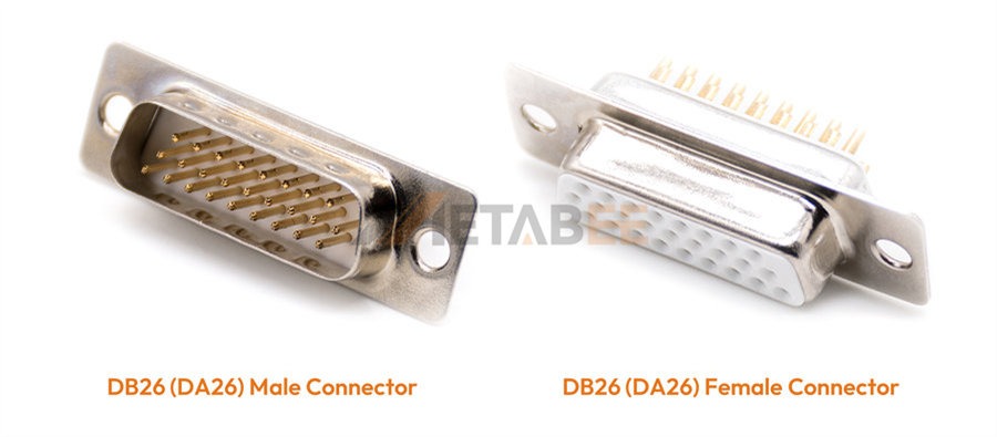
DA26 or DB26 Connectors (A-size shell, 26 contacts)
Fitting the A-size shell, the HD-26 connector offers 11 more signal lines than its standard equivalent. This capacity makes it an excellent medium-to-high density solution for compact enclosures and specialized networking hardware.
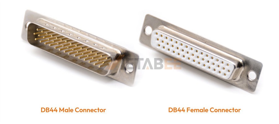
DB44 Connectors (B-size shell, 44 contacts)
With a B-size shell, the DB44 connector almost doubles the contact count of the standard DB-25. This density is valuable for industrial machinery interfaces, multi-axis motion control, and complex sensor applications requiring robust, high-channel count connectivity.
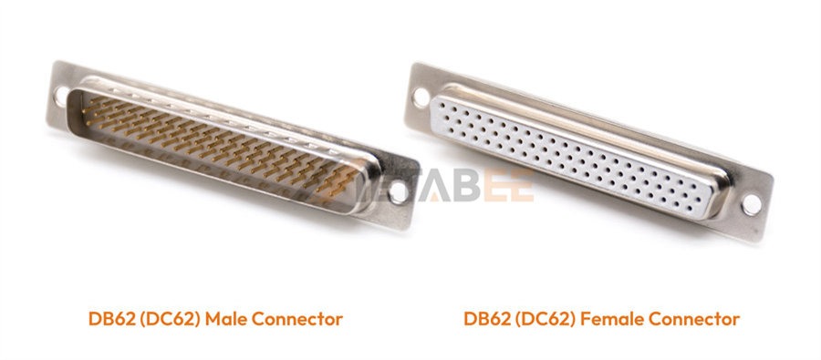
DC62 or DB62 Connectors (C-size shell, 62 contacts)
Offering 62 signals within the C-size footprint, the DB62 Connector is essential for applications that require a high number of interconnected channels. As a result, it is frequently specified for use in high-performance Automated Test Equipment (ATE), flight simulators, and sophisticated medical diagnostic units.
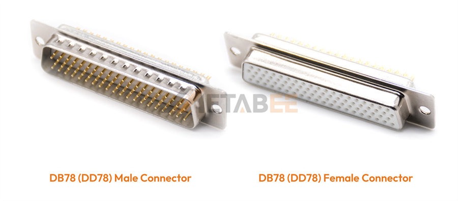
DD78 or DB78 Connectors (D-size shell, 78 contacts)
The high-channel-count DB78 connector is critical for telecommunications infrastructure, backplane designs, and demanding industrial control applications where integrating the maximum number of I/O lines into a rugged, shielded D-sub form is essential.
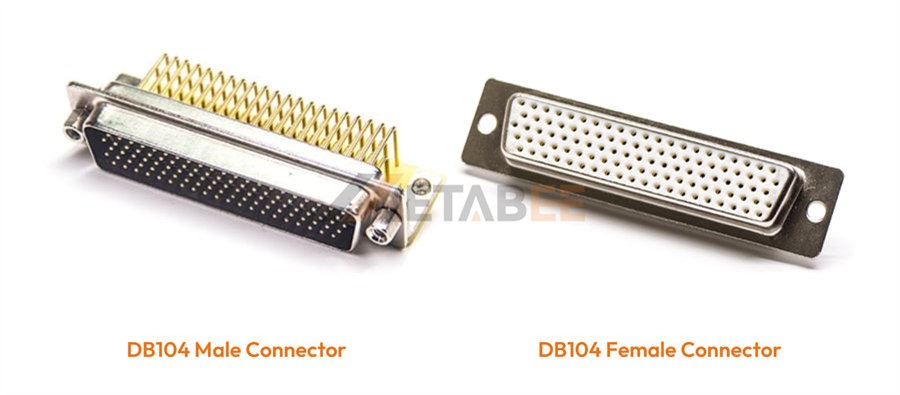
DB104 Connectors (6-size shell, 104 contacts)
Using the largest 6-size shell, the 104-pin D-sub connector provides 104 signal lines in a single interface. It is reserved for systems demanding the highest possible signal density in a fixed-footprint design.Typical applications include high-end data servers and specialized communication platforms.
Combo (Hybrid) D-Sub Connectors (24 Types)
The most advanced variation within the physical size classification is the Combo D-sub, also known as the Hybrid D-sub. Standard or high-density D-subs typically only carry low-current signals. In contrast, the Combo D-sub integrates different types of contacts—often referred to as 'inserts'—into a single D-sub shell.
The primary engineering challenge in system design is often managing multiple connectors (one for power, one for signal, one for RF) in a single interface panel. Combo D-subs solve this by consolidating diverse functions, significantly simplifying cable management and reducing panel space usage.
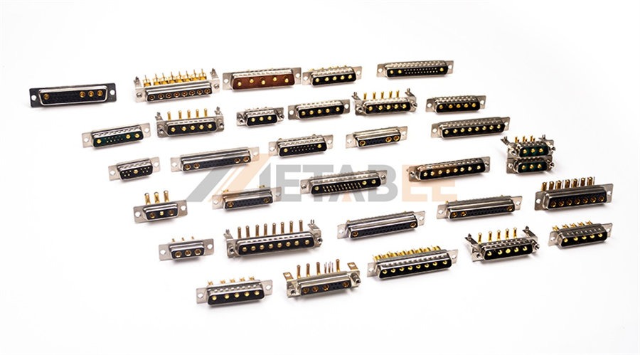
Metabee Combo D-sub Connectors
Key Types of Hybrid Contacts:
l Power Contacts: These are typically larger contacts capable of handling currents ranging from 10A up to 40A. They are crucial for supplying operating voltage to the connected equipment through the same connector used for data.
l Coaxial Contacts: Designed for high-frequency or RF signals, these contacts maintain proper impedance (50 or 75 ohms) for applications like video, broadcast equipment, or radar systems.
l High Voltage (HV) Contacts: Engineered with increased clearance and creepage distances within the insulator, these specialized contacts can safely transmit high DC or AC voltages, essential in applications like mass spectrometry or specialized industrial test gear.
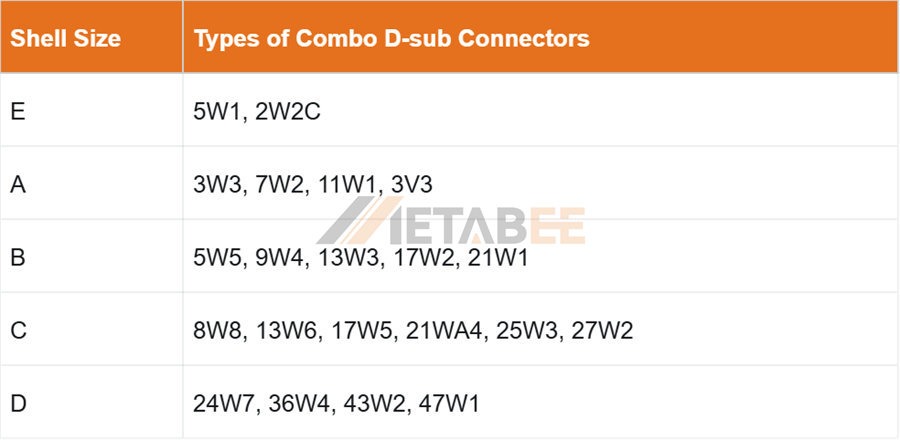
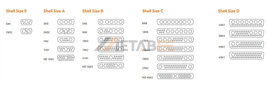
Typically, a Combo D-sub connector incorporates one or two types of specialty contacts. The various types of hybrid D-sub connectors are listed in the table below.
The contact arrangements for the various models of combo D-sub connectors are shown in the figure below.
Classification 2: By Termination Style
The second major category of D-sub connector types relates to how the electrical wires or the Printed Circuit Board (PCB) physically connect to the contacts within the housing. The termination style dictates ease of assembly, repairability, and mechanical stability.
Cable Termination Types (2 Types)
Cable termination methods define how a wire bundle is attached to the connector to form an external cable assembly.
Solder Cup
This is the most traditional and reliable method. Each contact features a small cup (or pot) at the back where the stripped wire is inserted and soldered.
- Pros: Creates a highly durable, low-resistance, and mechanically strong connection. Excellent for low-volume, high-reliability applications, and prototyping.
- Cons: Time-consuming to assemble and requires skilled soldering labor. Repair is possible but delicate.
Crimp
The crimp termination method involves attaching the wire to a specialized contact using a dedicated crimping tool, which mechanically deforms the contact around the conductor. The crimped contact is then snapped into the D-sub insulator housing.
- Pros: Ideal for high-volume manufacturing due to faster assembly time. Easier field repair/replacement since individual contacts can be removed and inserted using extraction tools.
- Cons: Requires precise tooling to ensure a gas-tight, reliable crimp.
PCB Termination Types (2 Types)
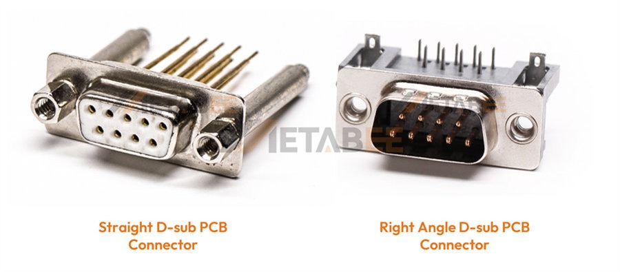
For connectors mounted directly onto a Printed Circuit Board (PCB) inside a device chassis, the classification is based on the orientation of the connector relative to the board. Both styles typically use solder-tail (through-hole) pins for robust mechanical attachment to the PCB.
Right Angle (90-Degree) Mount
This is arguably the most common PCB mount type, especially for rear-panel I/O. The connector is mounted so that the mating axis is perpendicular (90 degrees) to the PCB surface.
- Design Consideration: This positions the external cable parallel to the PCB, minimizing protrusion into the chassis and facilitating easy mating access on the equipment's exterior panel.
Straight (Vertical) Mount
The straight mount D-sub is positioned so the mating axis is parallel to the PCB surface. The connector points vertically away from the board.
- Design Consideration: Used when the cable must exit perpendicular to the PCB, often necessary in stacked board configurations or when panel space requires a vertical component layout.
Classification 3: By Performance and Specialty
Beyond size and termination, the environment and electrical demands of an application necessitate specialty D-sub connector types engineered for specific high-performance characteristics.
Filtered D-Sub Connectors
In today’s electronically noisy world, signal integrity is paramount. Filtered D-sub connectors are designed specifically to suppress Electromagnetic Interference (EMI) and Radio Frequency Interference (RFI) that can corrupt data transmission.
- Purpose: These connectors integrate filtering components—typically planar capacitors, ferrite beads, or lossy films—directly into the contact paths. These components shunt high-frequency noise and transients to the connector shell (ground), allowing only the desired low-frequency signal to pass.
- Use Case: Critical in sensitive environments such as medical imaging equipment, high-speed automated test equipment (ATE), avionics, and military communication systems where interference is unacceptable. Specifying a filtered D-sub often replaces the need for bulky external filtering components.
Waterproof & Hermetically Sealed D-Sub Connectors
For applications beyond controlled environments, D-sub connectors are specially engineered to withstand physical threats like dust, moisture, and extreme pressure differentials. These solutions fall into two main categories:
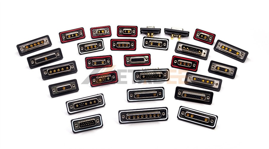
Waterproof/IP-rated: The acronym IP stands for Ingress Protection, and it’s a crucial rating for equipment used outside of climate-controlled environments. These connectors, commonly rated IP67, utilize specialized sealing gaskets, backshells, and o-rings to form a watertight and dust-proof barrier when mated. This feature is crucial for industrial environments, marine equipment, and factory automation, where washdowns or heavy dust are common.
Hermetically Sealed: These are reserved for systems requiring an absolute seal against gas or fluid leakage across a pressure boundary (e.g., in a vacuum or high-pressure system). This is achieved by sealing the contacts into the housing using specialized glass-to-metal technology, creating a molecular bond that ensures an extremely low leak rate, essential for deep-space applications, down-hole drilling, and laboratory vacuum chambers.
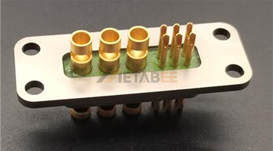
Custom Hermetically Sealed Combo D-sub Connector
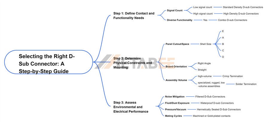
Selecting the Right D-Sub Connector: A Step-by-Step Guide
Navigating the multitude of available D-sub connector types can be complex, but following a structured decision process based on function, physics, and environment will ensure you make the optimal choice.
Step 1: Define Contact and Functionality Needs
Start with the electrical requirements of the system:
1. Signal Count: How many signal lines are required?
Decision: If the signal count is low (e.g., 9-50), a Standard Density D-sub is sufficient.
Decision: If space is limited but signal count is high (e.g., 62 signals in a small space), opt for High Density (HD).
2. Diverse Functionality: Does the interface need to handle power, high-frequency data, or high voltage alongside standard signals?
Decision: If yes, a Combo (Hybrid) D-Sub is mandatory to consolidate functions and save space.
Step 2: Determine Physical Constraints and Mounting
Next, consider the mechanical constraints of the equipment and the assembly process:
1. Panel Cutout/Space: What is the available mounting space on the chassis?
Decision: This determines the necessary shell size (E, A, B, C, D) and dictates whether a standard or high-density count is needed.
2. Board Orientation: How will the connector integrate with the PCB?
Decision: Right Angle for chassis rear-panel I/O. Straight (Vertical) for internal stacking or specific vertical port needs.
3. Assembly Volume: Are you producing hundreds of thousands of cables or prototypes?
Decision: Crimp for high-volume manufacturing and field serviceability. Solder Cup for specialized, rugged, low-volume assemblies.
Step 3: Assess Environmental and Electrical Performance
Finally, the application environment dictates the necessary specialty features:
1. Noise Mitigation: Is the device sensitive or located near powerful motors or RF sources?
Decision: Filtered D-Subs are essential to maintain signal integrity by suppressing EMI/RFI.
2. Fluid/Dust Exposure: Will the equipment be subject to industrial dust, water spray, or temporary immersion?
Decision: Specify an Industrial/IP-Rated D-Sub (e.g., IP67) with sealing backshells.
3. Pressure/Vacuum: Is the connector bridging a pressure boundary, such as a sealed enclosure, altitude chamber, or vacuum vessel?
Decision: Only a Hermetically Sealed D-Sub can provide the required leak-tight seal.
4. Mating Cycles: Does the application require frequent mating and unmating (e.g., test benches)?
Decision: Look for connectors with specialized contact plating (e.g., higher quality gold flash or plating thickness) to ensure longevity and low contact resistance over thousands of cycles.
Conclusion: Your Connection Solution
The D-sub connector’s versatility is its greatest asset, but that versatility demands careful consideration from the specifier. We've explored the 3 core classification pillars that define the universe of D-sub connector types. These pillars include Physical Size and Function, which covers Standard, High Density, and Combo variants. The other two pillars are Termination Style (Cable and PCB Mount) and Environmental Performance (Filtered and Waterproof).
By systematically analyzing your project’s needs against these categories, you move beyond simply asking, "how many pins do I need?" This systematic approach helps guarantee the necessary electrical reliability and mechanical durability of the final product. Ultimately, this process leads to a solution that ensures long-term cost-effectiveness.
Need help navigating the nuances between high-density, filtered, and combo D-sub types for your specific project? Contact our engineering team for application-specific consultation—we’re here to ensure your connectivity solution is built to last.
Related Products
- D-sub Connectors
- Standard-Density D-sub Connectors
- DB9 Connectors
- DB15 Connectors
- DB25 Connectors
- DB37 Connectors
- DB50 Connectors
- High-Density D-sub Connectors
- HD15/VGA Connectors
- DB26 Connectors
- DB44 Connectors
- DB62 Connectors
- DB78 Connectors
- DB104 Connectors
- Combo D-sub Connectors
- Waterproof D-sub Connectors
Frequently Asked Questions (FAQ)
Q: What are the three core classification pillars for D-sub connectors?
A: The D-sub connector universe is fundamentally defined by three classification pillars: Physical Size and Function (Standard, High Density, Combo), Termination Style (Cable Mount, PCB Mount), and Environmental Performance (Filtered, Waterproof and Hermetically Sealed).
Q: What is the main structural difference between Standard Density and High Density (HD) D-sub connectors?
A: Standard Density D-subs place contacts in two staggered rows with a standard contact pitch of 2.77mm (0.109 inch). High Density (HD) D-subs utilize the same physical shell sizes but place contacts in three staggered rows, reducing the contact pitch to 2.29mm (0.090 inch) to maximize signal capacity in a constrained space.
Q: What is the primary purpose of a Combo (Hybrid) D-Sub connector?
A: Combo D-sub connectors are designed to integrate different types of contacts (such as power contacts, coaxial contacts, high voltage contacts, and standard signal pins). All these elements are consolidated into a single D-sub shell. This consolidation helps simplify cable management and significantly reduces the required panel space for multi-functional interfaces.
Q: When is it appropriate to choose a Crimp termination style over a Solder Cup termination?
A: Crimp termination is preferred for high-volume manufacturing due to its faster assembly time and superior ease of field repair/replacement, as individual contacts can be removed. Solder Cup provides a highly durable, low-resistance connection, ideal for low-volume, high-reliability applications and prototyping.
Q: Why is the distinctive D-shape of the D-sub connector shell so important?
A: The D-shape serves two critical purposes: it ensures correct polarization, meaning the connector can only be mated in one orientation (preventing damage), and it provides essential electromagnetic interference (EMI) shielding.
Q: Which standard D-sub connector is famously associated with the VGA video interface?
A: The HD-15 (High Density 15 contacts), which uses the small E-size shell, is the standard connector specified for VGA and SVGA analog video interfaces.
Q: What does the letter in the standard D-sub naming convention (e.g., DB-25, DE-9) indicate?
A: The letter (E, A, B, C, or D) refers to the physical shell size of the connector, while the accompanying number indicates the contact count within that shell size.
Q: What is the critical distinction between Waterproof and Hermetically Sealed D-subs?
A: Waterproof or IP-Rated (Ingress Protection) D-sub connectors use gaskets and sealing backshells to protect against external dust and moisture ingress (e.g., IP67). Hermetically Sealed D-subs use glass-to-metal technology to create a molecular bond, ensuring an absolute, leak-tight seal against pressure boundaries, such as those found in vacuum or high-pressure systems.
Q: What are Filtered D-Subs, and what is their primary function?
A: Filtered D-Sub connectors integrate filtering components (like planar capacitors or ferrite beads) directly into the contact paths. Their primary function is to suppress Electromagnetic Interference (EMI) and Radio Frequency Interference (RFI). By doing so, they maintain signal integrity in electronically noisy or sensitive environments (e.g., medical devices or avionics).
