
In the vast and interconnected world of electronics, connectors are the unsung heroes that enable seamless communication and signal transfer. Among the myriad of options available, the SMA connector stands out as a true workhorse, playing a critical role in countless radio frequency (RF) applications. Whether you’re a seasoned engineer, a hobbyist, or just curious about the components that power your wireless devices, understanding SMA connectors is key to unlocking the full potential of RF technology.
This comprehensive guide will take you on a deep dive into the world of SMA connectors, covering everything from their basic concepts and history to their intricate structure, performance parameters, diverse classifications, and practical selection tips. We’ll also explore leading manufacturers and related products, ensuring you have all the knowledge you need to confidently navigate the RF landscape.
Introduction to SMA Connectors
What is an SMA Connector?
SMA (SubMiniature Type A) connector is a type of coaxial RF connector specifically designed for high-frequency applications, primarily in the microwave and millimeter-wave ranges. What does "coaxial" mean? It refers to the concentric arrangement of its conductors – an inner conductor surrounded by an insulating dielectric material. The insulator is then surrounded by an outer conductor. All parts share the same axis. This design is crucial for minimizing electromagnetic interference and signal loss at high frequencies.
The defining characteristic of an SMA connector is its threaded coupling mechanism. This threaded nut ensures a robust, secure, and highly reliable connection, which is vital for maintaining consistent electrical contact and minimizing signal degradation, especially in environments prone to vibration or movement. Its relatively compact size, coupled with its excellent electrical performance, has made it a go-to choice in a wide array of devices where dependable RF signal integrity is paramount and space is often at a premium.

A Brief History of SMA Connector Development
The development of the SMA connector traces back to the early 1960s, a period of rapid advancement in microwave technology. Engineers at Bendix Scintilla (now Amphenol) were instrumental in its creation. The need for a small, high-frequency connector that could reliably operate in increasingly demanding applications drove its design. Its introduction marked a significant step forward, offering superior performance compared to its predecessors and quickly gaining widespread adoption across various industries.
- Early 1960s: Developed by Bendix Scintilla (later Amphenol), introducing the essential threaded coupling and coaxial design for microwave applications.
- 1965: Formal MIL-spec documentation for SMA (initially OSM) is established, standardizing the interface and boosting industry-wide adoption.
- 1981: Southwest Microwave (SMI) develops the "SuperSMA," an advanced, field-replaceable version with stabilized Teflon, significantly improving high-temperature performance and reliability, especially for critical applications. This innovation spurred broader industry adoption of high-performance field-replaceable types.
- Mid-1990s: Reverse Polarity SMA (RP-SMA) emerges, primarily for Wi-Fi devices, as a regulatory measure.
- Present Day: SMA remains a cornerstone in RF/microwave systems, with ongoing advancements in precision (e.g., for 40 GHz), durability, and environmental performance, serving critical roles in 5G, satellite, and test applications.

Industry Standards and Specifications
The success and widespread interoperability of SMA connectors can largely be attributed to the adherence to rigorous industry standards. The most significant of these is MIL-STD-348, specifically MIL-STD-348B, which is a military standard that defines the precise dimensions and interface requirements for SMA connectors.
What does this standardization mean in practical terms? It ensures that an SMA male connector from one manufacturer will reliably mate with an SMA female connector from another. And their electrical performance characteristics will be consistent within defined tolerances.
These standards cover critical aspects like:
- Mechanical Dimensions: Ensuring physical compatibility.
- Material Requirements: Specifying the types of materials for conductors, dielectrics, and body.
- Electrical Performance Targets: Setting benchmarks for impedance, VSWR, and frequency range.
Besides, SMA connectors are also standardized according to specifications like MIL-PRF-39012 and CECC 22110/111.
Metabee's SMA connectors are designed to adhere to diverse industry standards, ensuring broad compatibility and reliability.
Key Features and Advantages of SMA Connectors
SMA connectors boast several key features that contribute to their popularity:
- Compact Size: Their subminiature design makes them suitable for applications where space is limited.
- Threaded Coupling: This mechanism provides excellent mechanical stability, preventing accidental disconnections and ensuring a secure electrical contact.
- High Frequency Performance: SMA connectors are designed to operate effectively up to 18 GHz, with some specialized versions extending beyond 26.5 GHz, making them ideal for microwave and millimeter-wave applications.
- Low VSWR (Voltage Standing Wave Ratio): A low VSWR indicates minimal signal reflection, leading to efficient power transfer and reduced signal loss.
- Good Durability: Constructed from robust materials, SMA connectors can withstand numerous mating cycles, offering long-term reliability.
Common Applications Across Various Industries
The versatility of SMA connectors is evident in their widespread use across diverse industries:
- Telecommunications: From Wi-Fi antennas and cellular base stations to satellite communication systems.
- Test and Measurement: Used extensively in oscilloscopes, spectrum analyzers, and network analyzers for precise RF measurements.
- Aerospace and Defense: Essential in radar systems, avionics, and military communication equipment due to their reliability in harsh environments.
- Medical: Found in various diagnostic and therapeutic devices that utilize RF signals.
- Automotive: Increasingly used in advanced driver-assistance systems (ADAS) and in-vehicle communication.
- Consumer Electronics: Though less visible, they might be present in some high-end networking equipment or specialized devices.
Structure and Materials of SMA Connectors
While the exterior of an SMA connector might appear simple, its internal design is a marvel of precision engineering. Each component plays a crucial role in ensuring optimal electrical performance and mechanical integrity. Understanding this internal anatomy, along with the specific materials used, is key to appreciating why SMA connectors perform so reliably at high frequencies.
An SMA connector is a finely tuned assembly of 3 distinct parts: outer shell, insulator, and center contact. All these parts work in harmony to maintain the coaxial structure and facilitate signal transmission. Let's break down the primary components and materials:
Outer Shell (Body)
Function
This is the most visible part of SMA connector, forming the outer cylindrical shell. Electrically, it serves as the ground path for the RF signal and provides crucial electromagnetic shielding. It prevents interference from external sources and containing the signal within the connector. Mechanically, it forms the main structural support for the entire connector and houses the threaded coupling mechanism.
Design Variations
The outer conductor can be designed for various mounting styles:
- Cable Mount: Features a crimp barrel or solder cup at one end to attach to the outer braid or jacket of a coaxial cable.
- Panel Mount: Includes a flange or nut for secure attachment to an equipment chassis or panel.
- PCB Mount: Designed with specific pins or pads for soldering directly onto a printed circuit board.
Material Interaction
The material of the outer conductor is chosen for its electrical conductivity and mechanical strength, typically brass or stainless steel, which are then plated with gold or nickel for enhanced performance.
Center Contact (Pin/Socket)
Function
This is the heart of the SMA connector, a slender pin (for male connectors) or a small socket (for female connectors) located precisely in the center. It carries the primary RF signal. Its precise dimensions and concentric alignment with the outer conductor are paramount for maintaining the characteristic impedance of the connector (50 Ohms). Any deviation here can lead to signal reflections and performance degradation.
Connection Method
For cable-mounted connectors, the inner conductor is typically soldered or crimped directly to the central conductor of the coaxial cable. For PCB mount versions, it will be a pin designed for through-hole soldering or a pad for surface mount attachment.
Material
Often made from brass or beryllium copper, chosen for their excellent electrical conductivity and resilience. They are almost always plated with gold for superior contact resistance and corrosion prevention, especially given the critical electrical contact it makes.
Dielectric Material (Insulator)
Function
Positioned between the inner and outer conductors, the dielectric material is an electrical insulator that prevents the two conductors from short-circuiting. Critically, it also plays a direct role in determining the connector's characteristic impedance. The material's dielectric constant and the precise dimensions of the inner and outer conductors define this impedance.
At high frequencies, any loss within the dielectric material can lead to significant signal attenuation. Therefore, materials with very low dielectric loss are essential.
Material Choice
The overwhelming majority of high-quality SMA connectors utilize PTFE (Polytetrafluoroethylene), commonly known by its brand name Teflon. PTFE is prized for its extremely low dielectric constant (around 2.1), excellent low-loss properties across a broad frequency spectrum, high temperature resistance, and chemical inertness. Other materials like glass or ceramic might be used in specialized, extremely high-frequency, or high-temperature applications. But PTFE remains the industry standard for most SMA connectors.

At Metabee, we meticulously select the best materials for our SMA connectors, guaranteeing their superior performance.
Understanding SMA Connector Parameters: Performance and Reliability
Beyond their physical structure, the true value of an SMA connector lies in its ability to perform reliably under specific electrical, mechanical, and environmental conditions. These performance parameters are critical metrics that engineers evaluate when selecting a connector for a given application. A deep understanding of these specifications ensures optimal signal integrity, system longevity, and overall product reliability.
Electrical Performance Parameters
- Impedance (50 Ohm): The impedance of an SMA connector is almost universally 50 Ohms. This impedance is crucial for matching the connector to the RF cable and the rest of the system to prevent signal reflections and maximize power transfer.
- Frequency Range: This specifies the range of frequencies over which the connector can operate effectively. It is typically up to 18 GHz for standard SMA, and DC to 26.5 GHz for precision versions.
- VSWR (Voltage Standing Wave Ratio): A measure of how well the connector is matched to the system impedance. A VSWR of 1.0:1 indicates a perfect match with no reflections. In reality, values like 1.3:1 or 1.5:1 are common and acceptable for many applications. Straight SMA connectors typically have a VSWR of 1.3 or less, while right angle SMA connectors generally have a VSWR of 1.5 or less.
- Insertion Loss: The amount of signal power lost as it passes through the connector. Measured in decibels (dB), a lower insertion loss is always better, indicating less signal degradation. SMA connectors are known for their low insertion loss. Typical values range from 0.1 dB to 0.5 dB.
- Power Handling: The maximum RF power the connector can safely transmit without sustaining damage or significant performance degradation. This is crucial for high-power applications.

Mechanical Performance Parameters
- Durability/Mating Cycles: The number of times the connector can be mated and unmated without significant degradation in electrical or mechanical performance. Standard SMA connectors are typically rated for 500 mating cycles.
- Coupling Torque: The recommended torque to apply when tightening the coupling nut to ensure a secure and reliable connection without over-tightening and damaging the connector. To ensure optimal performance and a secure connection, Metabee SMA connectors require a minimum coupling torque of 30 in-lbs.

Environmental Performance Parameters
- Operating Temperature Range: The range of temperatures over which the connector can function reliably without significant performance degradation. Typical ranges are wide, often from -65°C to +155°C.
- Vibration Resistance: The connector's ability to withstand mechanical vibration and sudden impacts without losing electrical contact or suffering structural damage, crucial for mobile and ruggedized applications. SMA connectors must be qualified for vibration resistance according to MIL-STD-202 Method 204.
- Corrosion Resistance: The ability of the connector's materials and plating to resist degradation from moisture, chemicals, and other corrosive elements in the operating environment. To ensure adequate corrosion resistance, SMA connectors are required to comply with MIL-STD-202 Method 101.
Classifying SMA Connectors: 9 Types of SMA Connectors You Need to Know
Classification by Polarity and Gender
Standard Polarity (Male/Female)
- SMA Male (Plug): Features a center pin (inner conductor) and an internal threaded coupling nut.
- SMA Female (Jack/Receptacle): Features a center sleeve (inner conductor) and an external threaded barrel.
This is the traditional and most common configuration.
Reverse Polarity (RP-SMA Male/Female)
- RP-SMA Male (Plug): Has a center sleeve (like a standard female) and an internal threaded coupling nut.
- RP-SMA Female (Jack/Receptacle): Has a center pin (like a standard male) and an external threaded barrel.
RP-SMA connectors were initially developed to prevent consumers from easily swapping antennas on Wi-Fi devices, acting as a form of "copy protection." It's important to note that standard SMA will NOT mate with RP-SMA.

Classification by Mounting Style
Panel Mount SMA Connectors
Panel mount SMA connectors are designed to be mounted through a hole in a panel or enclosure. They typically have a 4-hole flange or nut for secure attachment and often feature O-rings for environmental sealing.
SMA PCB Mount Connectors
SMA PCB connectors are designed to be soldered directly onto a PCB.There are to kinds of SMA PCB connectors:
- Through-Hole: Pins pass through holes in the PCB and are soldered on the opposite side.
- Surface Mount (SMT): Designed to be soldered directly onto the surface pads of the PCB, allowing for automated assembly and higher density packaging.
Cable Type SMA Connectors
Cable type SMA connectors are designed to be attached directly to the end of a coaxial cable. They come in various types depending on the cable diameter and construction (e.g., crimp, solder, clamp).

Classification by Orientation
- Straight: The connector extends straight out from the mating surface, maintaining the axial alignment of the cable.
- Right Angle: The connector bends at a 90-degree angle from the mating surface, useful for space-constrained applications or for routing cables neatly.
Choosing the Right SMA Connector: A Practical Guide
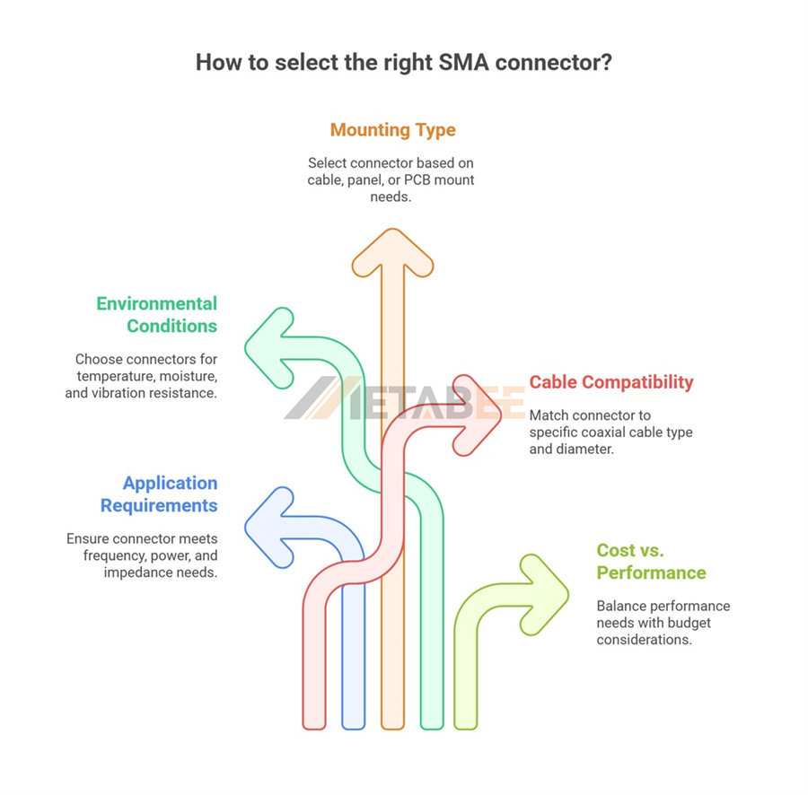
Selecting the appropriate SMA connector is critical for optimal system performance and reliability. Consider the following factors:
Factors to Consider When Selecting an SMA Connector
1. Application Requirements:
- Frequency Range: Ensure the connector's operating frequency range meets or exceeds your system's highest operating frequency.
- Power Handling: Verify that the connector can safely handle the maximum RF power your system will transmit.
- Impedance: Always choose 50-Ohm SMA connectors to match typical RF system impedance.
2. Environmental Conditions:
- Temperature: Select connectors rated for your expected operating temperature range.
- Moisture/Corrosion: For outdoor or harsh environments, opt for connectors with enhanced sealing (e.g., hermetically sealed) and superior plating for corrosion resistance.
- Vibration/Shock: In high-vibration or shock environments, choose ruggedized connectors with robust mechanical designs.
3. Mounting Type:
Determine whether you need a cable mount, panel mount, or PCB mount connector based on your product design.
4. Cable Compatibility:
Ensure the connector is designed for your specific coaxial cable type and diameter. Different cable types (e.g., RG-174, RG-316, RG-58, LMR-series) require specific connector designs.
5. Cost vs. Performance Trade-offs:
While precision connectors offer superior performance, they come at a higher cost. Balance your performance needs with your budget. For less critical applications, a standard commercial-grade connector might suffice.
Tips for Ensuring Optimal Performance and Longevity
- Proper Installation: Always follow the manufacturer's installation instructions, especially regarding crimping or soldering techniques for cable connectors and proper torque for threaded connections.
- Cleanliness: Keep connector interfaces clean and free of dust, dirt, and moisture, as contaminants can degrade performance.
- Avoid Over-tightening: Over-tightening the coupling nut can damage the connector, especially the internal dielectric, leading to degraded performance. Use a torque wrench if precision is critical.
- Minimize Mating Cycles: While durable, excessive mating and unmating can eventually wear out the connectors.
7 Leading SMA Connector Manufacturers
While the core specifications of SMA connectors are standardized, the quality, precision, and innovative offerings from different manufacturers can vary significantly. Choosing a reputable manufacturer is as important as selecting the right connector specifications, as it ensures product reliability, consistent performance, and often, better technical support. This section highlights 7 leading manufacturers in the SMA connector market.
- Amphenol RF: A global leader in interconnect solutions, Amphenol has a deeply intertwined history with coaxial connectors, including the SMA.
- TE Connectivity (TE): A major global technology leader known for its vast array of sensors and connectors.
- Hirose Electric (HRS): This prominent Japanese manufacturer is highly regarded for its precision, quality, and diverse range of connectors.
- Rosenberger: A leading German innovator in high-frequency and fiber optic connectivity.
- Molex: A global electronics leader, Molex offers a comprehensive range of interconnects, including a significant presence in the RF connector market.
- Renhotec: Based in China, Renhotec is a growing manufacturer specializing in a wide variety of electronic connectors, including RF connectors like SMA. They focus on providing cost-effective solutions for diverse commercial and industrial applications, emphasizing flexibility in design and volume production.
- Metabee: A prominent manufacturer, noted for its focus on manufacturing high-quality connectors and cable assemblies. Metabee aims to provide reliable and competitively priced SMA connectors, often serving telecommunications, networking, and general electronics markets.

Related Products

Conclusion: The Enduring Importance of SMA Connectors in Modern Electronics
The SMA connector, with its compact design, robust construction, and excellent high-frequency performance, has cemented its position as a cornerstone of modern RF and microwave systems. From the intricate circuits of satellites to the everyday convenience of Wi-Fi routers, its reliable connectivity enables the flow of information that drives our increasingly connected world.
Recap of Key Takeaways
We’ve covered the essential aspects of SMA connectors:
- Their fundamental role as 50-Ohm RF connectors for high-frequency applications.
- Their critical structure and material composition that ensure optimal electrical and mechanical integrity.
- The importance of electrical, mechanical, and environmental parameters in determining performance and reliability.
- The diverse classifications by polarity, mounting, and orientation, offering flexibility for various design needs.
- Practical considerations for selecting the right connector based on application requirements.
- The contributions of leading manufacturers who uphold the standards of quality and innovation.
- The symbiotic relationship with cable assemblies and adapters that complete the RF ecosystem.
Future Trends and Innovations in SMA Connector Technology
While the basic design of the SMA connector has remained largely consistent due to its effective standardization, innovations continue to push its boundaries. We're seeing:
- Extended frequency ranges for next-generation communication systems (e.g., 5G, 6G, and beyond).
- Improved manufacturing precision leading to even lower insertion loss and VSWR.
- Enhanced ruggedization for use in increasingly harsh and demanding environments.
- Miniaturization efforts for ultra-compact devices, though the SMA itself is already quite small.
- Integration with other technologies for more complex modular solutions.
As RF technology continues to evolve, the SMA connector will undoubtedly remain a vital component, adapting and innovating to meet the challenges and opportunities of future connectivity. Understanding its nuances empowers you to make informed decisions, ensuring the integrity and performance of your RF systems.
If you still need assistance in choosing the right SMA connector, please don't hesitate to reach out to us.
