
In the rapidly evolving landscape of telecommunications, aerospace, and industrial IoT, radio frequency (RF) systems demand uncompromising precision. At the heart of many of these high-frequency applications lies the SMA (SubMiniature version A) connector. Specifying the right connector goes beyond choosing a basic type. It requires a deep understanding of SMA connector dimensions.
Precision is non-negotiable. For hardware engineers, a millimeter of difference can cause a catastrophic system failure due to impedance mismatch or physical damage. Partnering with a reliable manufacturer like Metabee prevents these issues.
This comprehensive guide will walk you through the standard SMA connector size and exact SMA plug dimensions. We will contrast them with RP-SMA variations and provide a quick-reference SMA connector size chart. By understanding these interface dimensions, you can ensure optimal signal integrity and prevent costly mating mismatches.
Introduction to SMA Connectors
Engineers developed the SMA connector in the 1960s. It remains a semi-precision coaxial RF connector that operates exceptionally well from DC up to 18 GHz, while precision versions extend this performance up to 26.5 GHz. You will find them everywhere in microwave systems, Wi-Fi antennas, cellular base stations, and test equipment.
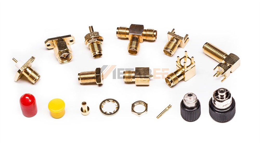
The reliability of an SMA connector relies heavily on its mechanical tolerances. Understanding exact dimensions is critical. Engineers sometimes overlook these dimensional nuances. This oversight often creates air gaps in the dielectric layer or causes excessive physical stress on the center contacts. Consequently, these issues degrade return loss and Voltage Standing Wave Ratio (VSWR).
Related Post: Beyond the Basics: Everything You Need to Know About SMA Connectors
Understanding the Standard SMA Interface
Junior engineers and buyers frequently ask: "Are all SMA connectors the same size?"
The short answer is no. Industry specifications, primarily MIL-STD-348, dictate a standardized interface. However, numerous variations exist in the market today. These include standard SMA, RP-SMA, and precision SMAs. Precision connectors like 3.5mm and 2.92mm remain physically compatible but feature different internal structures.
All true standard SMA connectors share a universal coupling mechanism. The defining feature of the SMA connector interface dimensions is its threaded coupling nut. The standard thread specification is 1/4-36 UNS-2A/2B.
What exactly does this technical designation mean? The "1/4" indicates a 0.250-inch major diameter. The "36" means the hardware features 36 threads per inch. "UNS" stands for the Unified National Special thread series. Finally, the "2A/2B" portion defines the strict tolerance class. Class 2A applies to the external threads on the female connector body. Class 2B applies to the internal threads on the male coupling nut. This precise classification guarantees a secure, vibration-resistant connection.
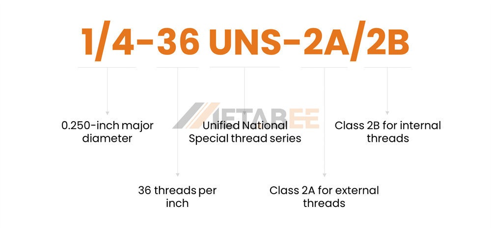
This standardized thread ensures that any standard SMA male will mechanically thread onto any standard SMA female. Mechanical threading, however, does not always guarantee electrical compatibility.
Standard SMA Connector Dimensions Deep Dive
Both the inner conductive elements and the outer mechanical housings must adhere to strict dimensional tolerances. This ensures a secure and electrically sound connection.
SMA Male Plug Dimensions
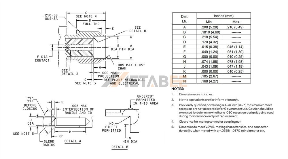
The SMA male connector features a center pin and an outer shell with interior threads. Manufacturers strictly define the SMA male plug dimensions to ensure a snug fit without damaging the female counterpart.
- Center Pin Diameter: The male center contact pin typically measures 0.90 to 0.94 mm (0.035 to 0.037 inches) in diameter.
- Pin Length: The pin must not protrude too far beyond the reference plane. This prevents "bottoming out" and destroying the female receptacle.
- Coupling Nut: The standard hex nut measures 5/16 inch (approx. 7.9 mm) across the flats. You need a specific 5/16" torque wrench to tighten it properly.
- Inner Housing: The inner diameter of the male outer conductor must seamlessly mate with the female's outer shell. This guides the center pin perfectly into the receptacle.
SMA Female Connector Dimensions
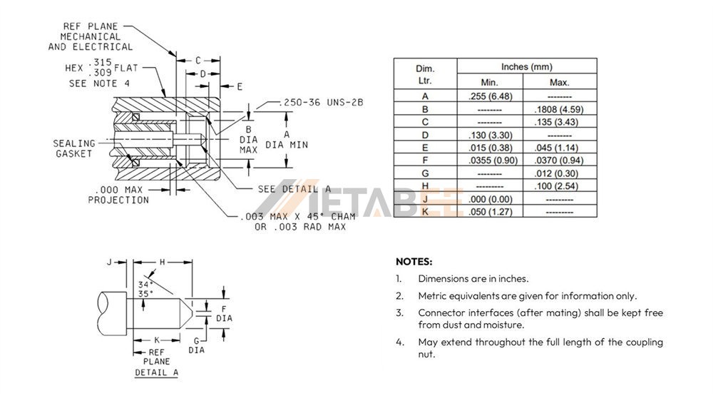
The SMA female connector consists of an outer housing with exterior threads. It also contains an inner center receptacle designed to accept the male pin.
- Outer Thread Diameter: The female SMA connector dimensions feature an outer thread diameter of exactly 1/4 inch (6.35 mm).
- SMA Female Diameter (Receptacle): The inner center contact is a slotted receptacle. Its inner diameter tightly grips the ~0.9 mm male pin.
- Mating Depth: The dielectric placement must perfectly align with the male reference plane. If the SMA female dimensions fall out of spec, the male pin might lack sufficient contact. This leads to intermittent signal drops.
Need help with component selection? Contact Metabee today to find precise SMA connectors tailored perfectly to your PCB layout and cable requirements.
SMA vs. RP-SMA: Navigating the Differences
Confusing standard SMA with RP-SMA remains a common and costly mistake in RF procurement.
What are RP-SMA Connectors?
RP-SMA stands for Reverse Polarity SMA. The FCC originally designed this interface to prevent consumers from attaching professional-grade antennas to home Wi-Fi equipment.
RP-SMA reverses the center contacts while keeping the outer threads exactly the same.
- Standard SMA Male: Inside threads + Center Pin
- Standard SMA Female: Outside threads + Center Receptacle
- RP-SMA Male: Inside threads + Center Receptacle
- RP-SMA Female: Outside threads + Center Pin
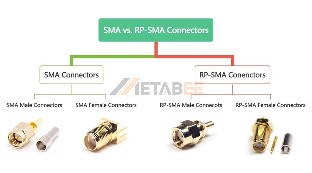
RP-SMA Connector Dimensions
The outer RP SMA connector dimensions match standard SMA connectors because the threads are identical. The actual difference lies entirely in the RP-SMA diameter of the inner contacts.
Look closely at the RP SMA female dimensions. It has outside threads but contains a standard ~0.9 mm male pin. Conversely, the RP SMA male dimensions feature an inner grip diameter designed to accept that pin.
Crucial Warning: Do not mate a standard SMA male to an RP-SMA male. They have incompatible center contacts and will not thread properly. Even worse, forcing a standard SMA male into an RP-SMA female will permanently crush and destroy both center pins. Always verify the inner interface dimensions before mating.
Related Post: SMA vs RP-SMA: Key Differences, Compatibility & How to Choose the Right Connector
Important Sizing Considerations for System Design
Engineers must consider the physical footprint of the connectors when designing system panels.
Maintaining the 50 Ohm Impedance
Almost all standard RF applications require a 50-ohm characteristic impedance to minimize signal reflection. Physical dimensions directly determine the impedance in a coaxial structure. Engineers calculate this characteristic impedance (Zo) using the following specific formula:
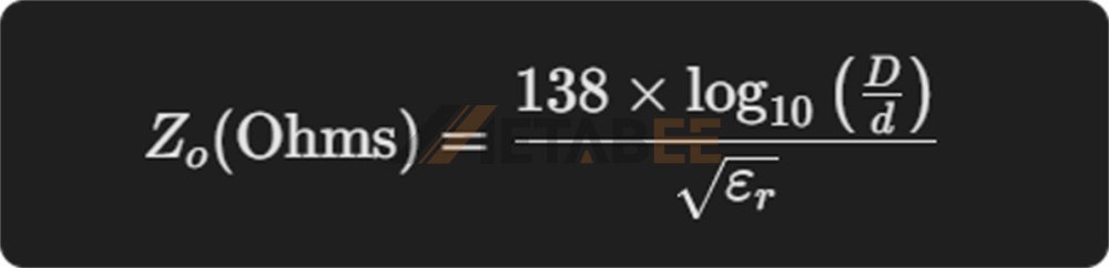
Here is what each variable represents in the connector's internal geometry:
- D: The inner diameter of the outer conductor.
- d: The outer diameter of the inner conductor (the center pin).
- ℇr: The dielectric constant of the insulating material (for standard PTFE, ℇr approx 2.1).
Therefore, any manufacturing flaw alters the standard SMA connector dimensions. Even a fraction of a millimeter changes the critical D/d ratio. This dimensional shift pushes the impedance away from 50 ohms and ruins your VSWR.
90 Degree SMA Connector Dimensions
Routing a stiff coaxial cable straight out of a dense board is often impossible. Engineers use right-angle connectors to solve this problem.
When evaluating 90 degree SMA connector dimensions, you must account for the specific height above the board. A typical right-angle SMA sits roughly 13.5 mm to 15 mm high.
Technical Note: The internal 90-degree bend inherently introduces a slight impedance mismatch. The outer SMA connector dimensions in mm might fit your enclosure perfectly. However, keep the internal structure in mind. A 90-degree connector typically produces a slightly higher VSWR at upper frequencies above 12 GHz compared to a straight connector.
Working on a space-constrained project? Request a quote from Metabee for our low-profile, high-performance right-angle SMA solutions.
Minimum SMA Connector Spacing
Minimum SMA connector spacing acts as a critical design parameter for multi-port RF devices.
How close can you place two SMA connectors side-by-side? The outer coupling nut requires a 5/16-inch (7.9 mm) wrench to tighten. You must leave enough clearance for this tool.
- Absolute Minimum Spacing: 9.5 mm (0.375 inches) center-to-center.
- Recommended Spacing: 12 mm to 14 mm. This provides adequate room for a standard torque wrench head. Technicians can apply the correct mating torque without scraping adjacent connectors.
Comprehensive SMA Connector Size Chart
We prepared this quick-reference SMA connector size chart to assist your mechanical design process.
|
Dimension Feature |
Metric (mm) |
Imperial (inches) |
Note |
|
Coupling Nut Thread |
1/4-36 UNS-2B |
1/4-36 UNS-2B |
Universal standard thread |
|
Coupling Nut Hex Size |
7.9 mm |
5/16 inch |
Requires 5/16" torque wrench |
|
Male Center Pin Diameter |
0.90 - 0.94 mm |
0.035 - 0.037 in |
Standard SMA Male & RP-SMA Female |
|
Female Receptacle ID |
~0.95 mm |
~0.037 in |
Designed to grip the male pin |
|
Outer Conductor Inner Dia. |
4.12 mm |
0.162 in |
Crucial for 50-ohm calculation |
|
Dielectric Diameter (PTFE) |
4.12 mm |
0.162 in |
Fills the space between conductors |
|
Mating Torque (Brass) |
0.34 - 0.56 N·m |
3 - 5 in-lbs |
Exceeding this damages the interface |
|
Mating Torque (Stainless) |
0.90 - 1.13 N·m |
8 - 10 in-lbs |
Standard for high-durability usage |
(Note: Exact tolerances vary slightly by MIL-STD-348 specifications. Always refer to the specific manufacturer's technical drawing).
Conclusion: Precision Matters in RF Connectivity
Understanding SMA connector dimensions guarantees the electrical and mechanical integrity of your RF systems. You might be routing traces on a dense PCB and calculating the minimum SMA connector spacing. Alternatively, you might be purchasing bulk cables and verifying SMA male dimensions. In all scenarios, the exact details matter.
Low-cost connectors often suffer from dimensional inaccuracies. These flaws lead to loose matings, impedance bumps, and eventual system failure under thermal stress.
Don't let a millimeter compromise your entire system's performance. Contact the Metabee engineering team today for expert technical support. We provide detailed 2D/3D CAD models, compliance documentation, and high-quality standard and RP-SMA connector samples tailored exactly to your requirements. Send us an inquiry to get started!
Related Products
Frequently Asked Questions (FAQs)
Q1: Are all SMA connectors the exact same size?
A: No. While standard SMA connectors share a universal 1/4-36 UNS threaded coupling mechanism, internal variations exist. The most common variation is RP-SMA (Reverse Polarity). Always verify the inner pin and receptacle configuration before mating to avoid damaging the contacts.
Q2: What is the minimum spacing required between SMA connectors on a panel?
A: The absolute minimum center-to-center spacing is 9.5 mm (0.375 inches). However, for practical installation, a spacing of 12 mm to 14 mm is highly recommended. This provides enough clearance for a standard 5/16-inch torque wrench.
Q3: How much torque should be applied to an SMA connector?
A: For brass SMA connectors, the recommended mating torque is 3 to 5 in-lbs (0.34 - 0.56 N·m). For stainless steel connectors, apply 8 to 10 in-lbs (0.90 - 1.13 N·m). Exceeding these limits can permanently deform the mechanical interface.
Q4: How do SMA connector dimensions affect the 50-ohm impedance?
A: The 50-ohm characteristic impedance relies strictly on the ratio between the inner diameter of the outer conductor and the outer diameter of the center pin (the D/d ratio). Even microscopic manufacturing flaws in these dimensions will alter the impedance and increase the VSWR.
Q5: Can I mate a standard SMA to an RP-SMA connector?
A: No. Standard SMA and RP-SMA connectors are incompatible. While the outer threads will physically fit together, their internal center contacts will either fail to connect or physically crush each other (pin-to-pin collision).
