
In the demanding world of industrial, military, and aerospace applications, reliable electrical connections are paramount. Among the myriad of connector types available, the MIL-DTL-5015 connector stands out as a time-tested and widely adopted solution. Renowned for its robust construction, exceptional durability, and resistance to harsh environmental conditions, the MIL-DTL-5015 series provides a secure and dependable means of transmitting power and signals across critical systems. This guide will delve into a crucial aspect of these connectors: their insert arrangements, explaining what they are, showcasing their diverse configurations, and highlighting the relationship between contact types, wire gauges, and their respective applications.
Introduction to MIL-DTL-5015 Connectors
In industries where failure is not an option, the integrity of electrical connections is non-negotiable. The MIL-DTL-5015 standard defines a family of circular electrical connectors that have become synonymous with ruggedness and reliability. Originating as a U.S. military standard, these connectors are engineered to withstand demanding conditions, including extreme temperatures, vibration, shock, and humidity. Their robust design typically features a threaded coupling mechanism, ensuring a secure and vibration-resistant connection.
MIL-DTL-5015 connectors are characterized by their sturdy aluminum alloy shells, which provide excellent mechanical protection and electromagnetic interference (EMI) shielding in some versions. The insulators within these shells are made from durable materials that offer high dielectric strength and resistance to environmental factors. These connectors are available in a wide range of shell sizes and insert arrangements, making them adaptable to a multitude of applications.
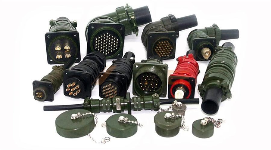
Metabee MIL-DTL-5015 Circular Connectors
The enduring popularity of MIL-DTL-5015 connectors stems from their proven track record of performance and dependability. Their standardized design ensures interchangeability between different manufacturers' products that meet the specification. This wide availability and the established reliability make them a preferred choice in diverse sectors, including:
l Military and Defense: Connecting critical systems in vehicles, aircraft, communication equipment, and weaponry.
l Aerospace: Used in aircraft avionics, engine controls, and other vital systems where reliability under extreme conditions is essential.
l Industrial Equipment: Providing robust connections for machinery, automation systems, power supplies, and control panels in demanding industrial environments.
l Transportation: Found in heavy-duty vehicles, railway systems, and marine applications.
l Test and Measurement: Used in laboratory and field equipment requiring reliable and durable connections.
Insert Arrangements of MIL-DTL-5015 Connectors
What are Insert Arrangements of MIL-DTL-5015 Connectors?
At the heart of a MIL-DTL-5015 connector's functionality lies its insert arrangement. This refers to the specific configuration of contacts within the connector's insulator. The insert arrangement dictates several key factors:
l Number of Contacts: The total number of individual electrical connections the connector can facilitate.
l Contact Size: The physical size of each contact cavity, which corresponds to the size and current-carrying capacity of the contacts that can be used.
l Contact Position: The precise location and orientation of each contact cavity within the insulator.
The insert arrangement is therefore a critical factor in selecting the right connector for a specific application. It must match the number and type of wires or cables that need to be connected.
The Structure of Insert Arrangement Numbers
The Insert Arrangement number for MIL-DTL-5015 connectors consists of two parts separated by a hyphen. The first part indicates the connector's shell size number. The second part is the contact arrangement code. It's important to note that the numbers in the second part do not represent the total number of contacts in the connector.
For example, consider a connector with the Insert Arrangement number 16S-8. In this designation, '16S' indicates the connector's shell size as 16S, and '8' represents its contact arrangement code. This particular arrangement has 5 contacts.
Insert Arrangement Diagrams
Before reviewing the Insert Arrangement Diagrams, it's important to understand the symbols for the different contact types used in MIL-DTL-5015 connectors, as shown in the diagram below.

Ins1. Insert Arrangement Diagrams for Shell Size 10S

2. Insert Arrangement Diagrams for Shell Size 12S

3. Insert Arrangement Diagrams for Shell Size 14S
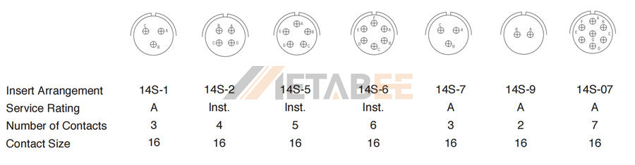
4. Insert Arrangement Diagrams for Shell Size 16S
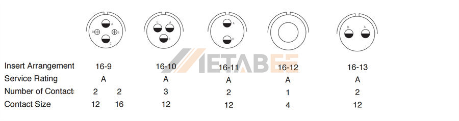
5. Insert Arrangement Diagrams for Shell Size 16
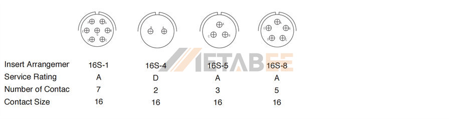
6. Insert Arrangement Diagrams for Shell Size 18
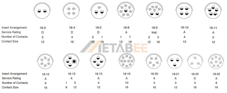
7. Insert Arrangement Diagrams for Shell Size 20
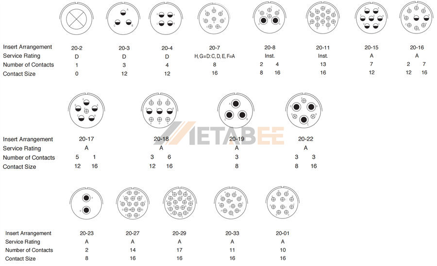
8. Insert Arrangement Diagrams for Shell Size 22
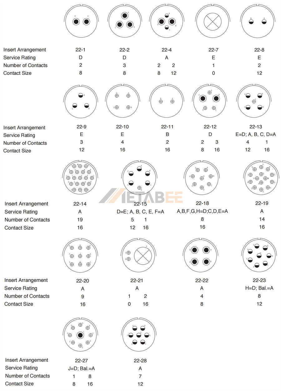
9. Insert Arrangement Diagrams for Shell Size 24
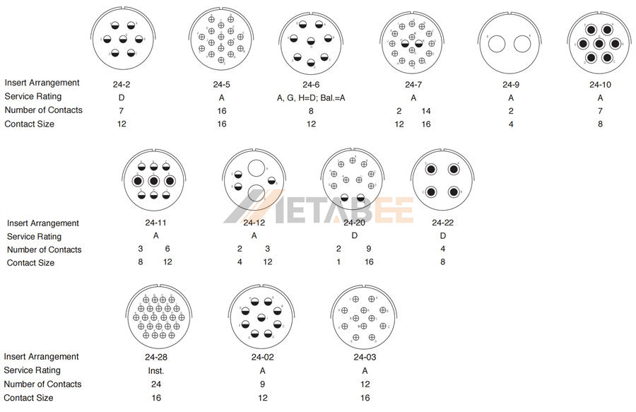
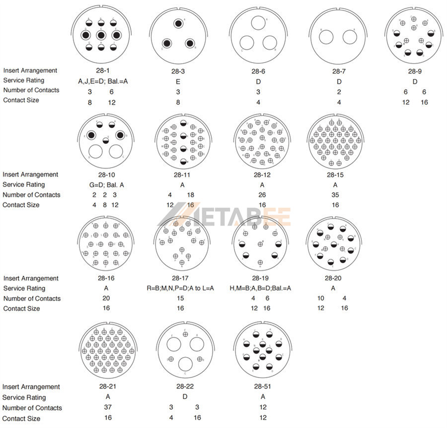
10. Insert Arrangement Diagrams for Shell Size 28
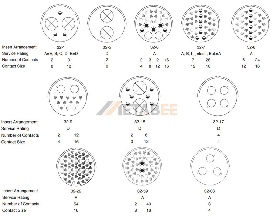
11. Insert Arrangement Diagrams for Shell Size 32
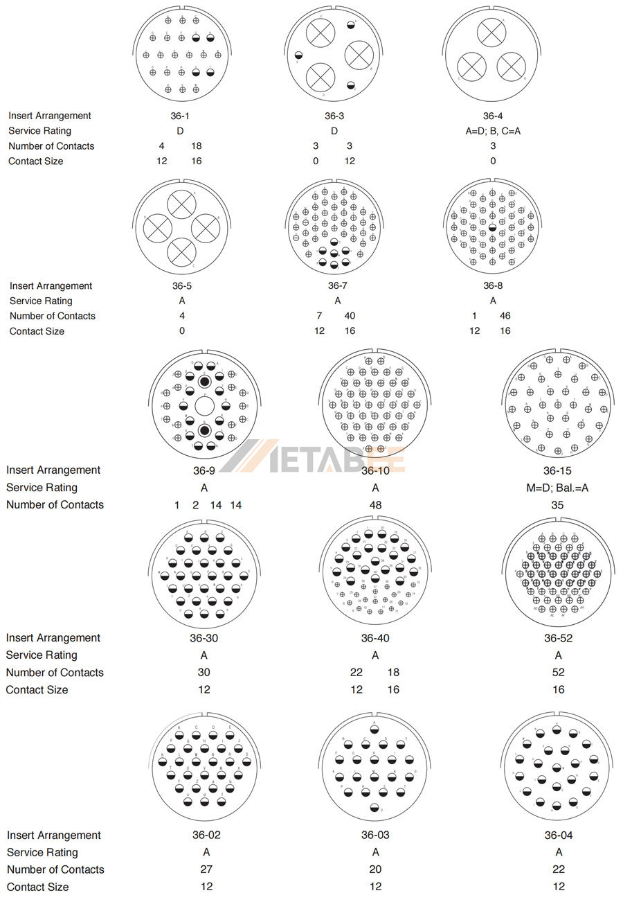
11. Insert Arrangement Diagrams for Shell Size 36
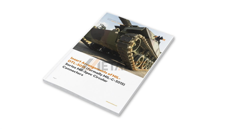
Download the PDF Copy of Insert Arrangement Diagrams
To make it easier to find the Insert Arrangement Diagrams for MIL-DTL-5015 connectors, I have specifically created a PDF document about MS5015 connector Insert Arrangements. If needed, you can download it by clicking the link below.
[PDF] Insert Arrangements of MIL-DTL-5015 Connectors – METABEE
Contact Types and Wire Gauges in MIL-DTL-5015 Connectors
The Insert Arrangement section of MIL-DTL-5015 defines the types of contacts and their arrangement within the connector. In this section, we will introduce five common contact types, along with their wire gauge compatibility.
Contacts used in MIL-DTL-5015 connectors are compliant with MIL-C-39029 specifications.
5 Types of Contacts for MIL-DTL-5015 Connectors
MIL-DTL-5015 connectors accommodate 5 types of contacts, each designed for specific termination methods and applications:
l Solder Contacts: These contacts feature a solder cup or pot at the wire termination end. Wires are stripped and soldered into these cups, creating a robust and reliable mechanical and electrical connection. Solder connections offer excellent resistance to vibration and are often preferred in harsh environments where a secure, permanent connection is required.
l Crimp Contacts: Crimp contacts have a barrel at the termination end. Wires are stripped and inserted into this barrel, which is then compressed using a specialized crimping tool. Crimp terminations offer a fast and consistent method of wire termination, making them ideal for field installations and high-volume production.
l PC Tail Contacts: Designed for direct soldering onto printed circuit boards (PCBs), these contacts have pins or tails that facilitate a direct electrical and mechanical connection between the connector and the PCB. PC tail contacts simplify wiring and reduce the need for separate wire terminations when connecting to electronic assemblies.
l Thermocouple Contacts: Used specifically for connecting thermocouple wires, these contacts are manufactured from specific alloys that match the thermoelectric properties of the thermocouple materials. This ensures accurate temperature signal transmission by minimizing the generation of unwanted thermal electromotive force (EMF) at the connection point.
l Coaxial Contacts: Designed for transmitting high-frequency signals, coaxial contacts maintain a specific impedance to ensure signal integrity and minimize signal loss and reflection. They are used with coaxial cables and are crucial in applications like radar, communication systems, and test equipment.
Wire Gauges
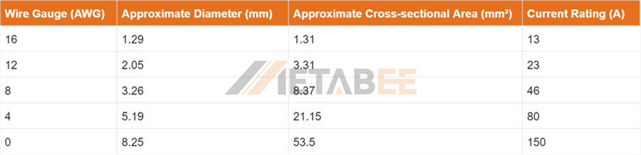
The size of the contact within the insert arrangement directly correlates with the wire gauge it is designed to accommodate. Wire gauge is a standardized measurement of wire thickness, typically expressed in American Wire Gauge (AWG) or square millimeters (mm²). Each contact size within a MIL-DTL-5015 connector has a specific range of wire gauges that can be reliably terminated.
The contacts available from METABEE for MIL-DTL-5015 connectors are compatible with wire gauges 0, 4, 8, 12, and 16 AWG. Due to their differing dimensions, these contacts feature the following current ratings: 13A (16 AWG), 23A (12 AWG), 46A (8 AWG), 80A (4 AWG), and 150A (0 AWG).
Conclusion: The Importance of Understanding Insert Arrangements
In conclusion, the insert arrangement is a fundamental aspect of selecting the right MIL-DTL-5015 connector for a specific application. It dictates the number and size of contacts the connector can accommodate, which in turn determines the types of wires that can be connected and the overall functionality of the electrical interface. Understanding the different insert arrangement designations and the corresponding contact types and wire gauge compatibility is essential for engineers and procurement professionals alike.
By carefully considering the specific requirements of your application – including the number of circuits, the type of signals or power being transmitted, and the required wire gauges – you can select the appropriate MIL-DTL-5015 connector with the ideal insert arrangement to ensure reliable, durable, and efficient electrical connections in even the most demanding environments. Remember to always refer to METABEE’s MIL-DTL-5015 catalog for guidance on selecting the correct connector components for your specific needs.
If you still need assistance in choosing the right MIL-DTL-5015 connector, please don't hesitate to reach out to us.
