
In the demanding field of Radio Frequency (RF) and microwave engineering, efficient high-frequency signal transmission is vital. While antennas and amplifiers capture the primary focus, the coaxial connector is the most critical, yet often underestimated, component determining total system efficiency. Ignoring a connector’s specifications—for frequency, impedance, or environment—guarantees severe signal loss, power degradation, and costly failures. Understanding diverse coax connector types and their intricate specifications is the non-negotiable first step toward building reliable, high-integrity systems.
What is a Coaxial Connector?
This section establishes the foundation of coaxial connectors, covering their essential definition, operational physics, historical development, and guiding industry standards.
The Definition
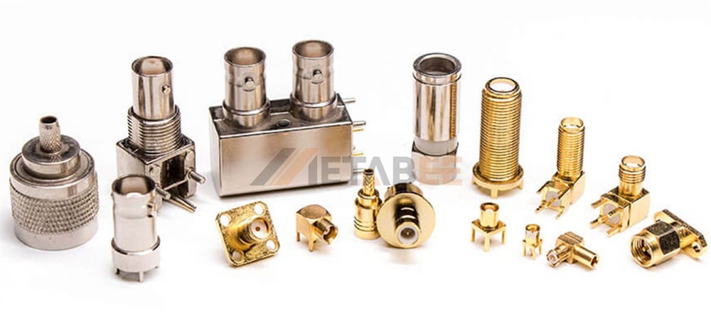
A coaxial connector is an electrical connector featuring a central signal conductor surrounded by a concentric conducting shield, with an insulating material separating the two. This concentric design is what gives it the common name, "coax." Its core function is to establish a secure, repeatable, and low-loss connection between two coaxial cables, or between a cable and an electronic device (such as a transmitter, antenna, or receiver). Crucially, coax connectors are engineered to maintain the cable's characteristic impedance throughout the connection point, a feature that distinguishes them from standard electrical plugs.
The Working Principle: Why Coaxial Matters
The effectiveness of a coaxial connector lies in its unique, concentric structure, which mimics the structure of the cable itself. This geometry consists of:
- A central contact that carries the signal.
- A dielectric insulator surrounds the central conductor.
- An outer shell that provides grounding and electromagnetic shielding.
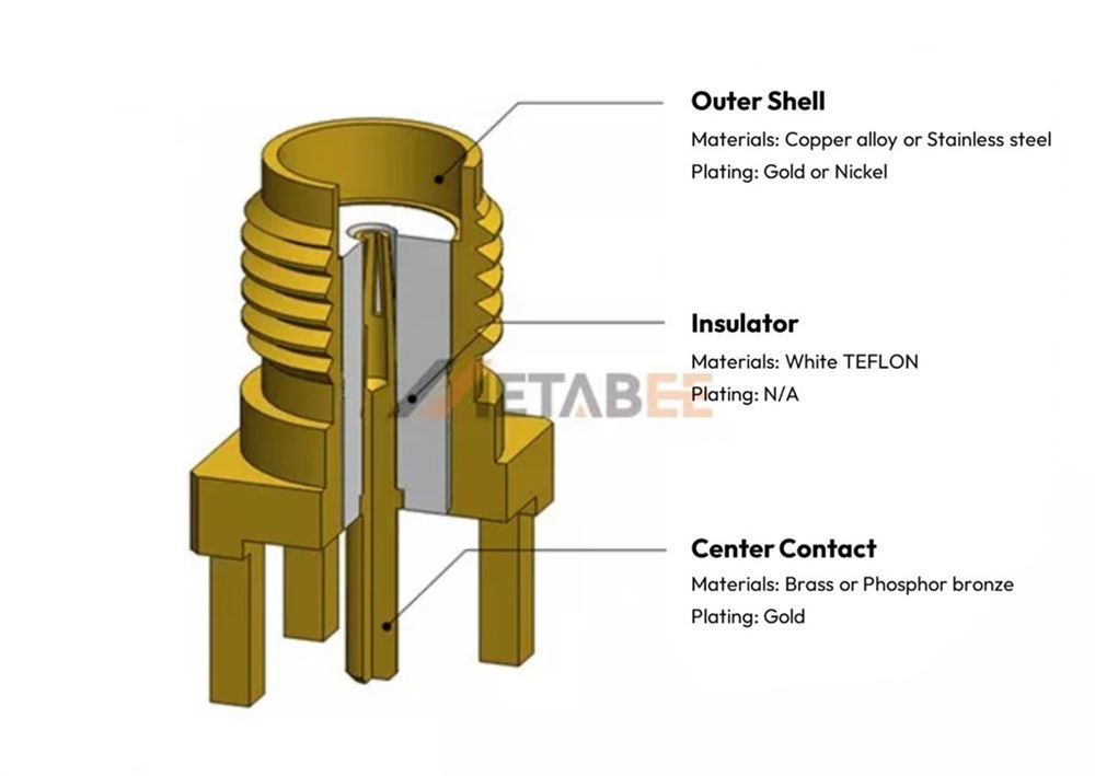
Structure and Materials of SMA Connectors
The coax connector maintains this geometric relationship, ensuring that the electrical properties—primarily the characteristic impedance (typically 50 Ohm or 75 Ohm)—remain constant across the junction. If this impedance match is not maintained, part of the high-frequency signal will reflect back towards the source, a phenomenon known as Return Loss or high VSWR (Voltage Standing Wave Ratio). High VSWR leads to reduced signal strength, increased heat, and system instability. Thus, the working principle of the coax connector is fundamentally about preserving impedance and shielding integrity.
A Brief History and Evolution
Coaxial connectors trace their lineage back to the 1930s with the invention of the N-Type connector by Paul Neill at Bell Labs, which was crucial for early radar technology during WWII. The BNC (Bayonet Neill–Concelman) soon followed, offering a quick-connect alternative for lower frequencies.
The evolution of coax connectors is a story of miniaturization and the relentless pursuit of higher operating frequencies. The telecommunications industry expanded into the microwave and millimeter-wave spectrum, a trend accelerated by the advent of satellite communication and modern 5G. This necessitated shrinking the physical size of connectors to accommodate shorter wavelengths and higher component densities on circuit boards. This necessity led to the development of the SMA, and later, the high-frequency precision RF connectors (2.92mm, 2.4mm, 1.85mm, and 1.0mm) that push well into the 110 GHz range.
Key Industry Standards
Standardization is vital in global trade and the usage of connectors, ensuring interchangeability and predictable performance across different manufacturers. The most important governing bodies and standards include:
- MIL-STD (Military Standard): Historically and currently crucial, particularly for demanding applications in defense and aerospace. MIL-C-39012 and MIL-STD-348 define the dimensional, electrical, and environmental performance requirements for many popular connector types (e.g., SMA, TNC, N-Type). MIL-DTL-17 is the governing standard for MIL-Spec coaxial cables.
- IEC (International Electrotechnical Commission): Global standards that provide common requirements for safety and performance, widely used in commercial and industrial sectors. The IEC 61169 series specifies the dimensional, electrical, and mechanical requirements, along with test methods, for various types of Radio-Frequency (RF) coaxial connectors. The IEC 60966 series defines the general and sectional specifications for the performance and testing of pre-assembled RF and coaxial cable assemblies.
Adherence to these standards is a non-negotiable factor when procuring connectors for professional, mission-critical systems.
Classification and Overview of Major Coax Connector Types
Coaxial connectors are classified based on several key design elements that dictate their suitability for different applications.
Based on Coupling Mechanism (Threading vs. Bayonet vs. Push-on)
The method by which the plug and jack connect profoundly affects mechanical stability, ease of use, and maximum operating frequency.
|
Coupling Mechanism |
Examples |
Advantages |
Disadvantages |
Typical Max Frequency |
|
Threaded |
N-Type, SMA, TNC |
Superior mechanical stability, excellent electrical performance, high vibration resistance. |
Slower connection process. |
Up to GHz (Precision Types) |
|
Bayonet |
BNC |
Ultra-fast connect/disconnect, ideal for frequent testing. |
Lower max frequency, less robust mechanical stability. |
Typically 4 GHz |
|
Push-on / Snap-on |
SMB, MMCX, SMP |
Quickest connection, highest density packaging (board-to-board). |
Lowest power handling, least mechanical retention. |
Up to 10 GHz (or higher with precision push-on) |

Based on Size / Frequency Range
A general rule in RF engineering dictates that as the signal frequency increases, the physical size of the transmission line components—including the connector—must decrease to minimize unwanted modes of transmission (modal interference) and leakage.
- Large (for high power/low frequency): Connectors like N-Type and 7/16 DIN are robust, handle high power, and are used primarily below 18 GHz, often for outdoor antenna systems.
- Medium (general purpose/mid-range frequency): BNC and TNC are the workhorses of test labs and general-purpose RF systems, typically operating in the DC to 11 GHz range.
- Small / Miniature (for high frequency/compact devices): SMA, SMB, MCX, and MMCX are the foundation of modern wireless devices, offering a balance between size, frequency, and cost, operating up to 26.5 GHz.
- Sub-Miniature / Precision (for very high frequency up to 110 GHz): The millimeter-wave regime is dominated by precision connectors like the 2.92mm (K), 2.4mm, 1.85mm (V), and 1.0mm. Their extremely tight tolerances are necessary to maintain signal integrity at ultra-high frequencies.

Coax Connector Types and Applications
A proper understanding of connector types involves knowing not only their name but their specific mechanical and electrical trade-offs.
General Purpose & Legacy Types
These connectors form the backbone of older systems, broadcasting, and general lab use.
|
Connector |
Coupling Mechanism |
Typical Impedance |
Max Frequency |
Key Applications |
|
BNC |
Bayonet |
50 Ohm or 75 Ohm |
4 GHz |
Test Equipment (oscilloscopes), CCTV, and Broadcast Video. |
|
N-Type |
Threaded |
50 Ohm |
18 GHz (some to 26.5 GHz) |
Base Station Antennas, Radar, High-Power RF Amplifiers. |
|
F-Type |
Threaded |
75 Ohm |
2 GHz |
Consumer Cable TV (CATV), Satellite TV (SATV), and Modems. |
|
UHF / Mini-UHF |
Threaded |
Non-constant Z / 50 Ohm |
300 MHz / 2.5 GHz |
Amateur Radio (Legacy), Automotive Communications. |
BNC (Bayonet Neill–Concelman) Connectors
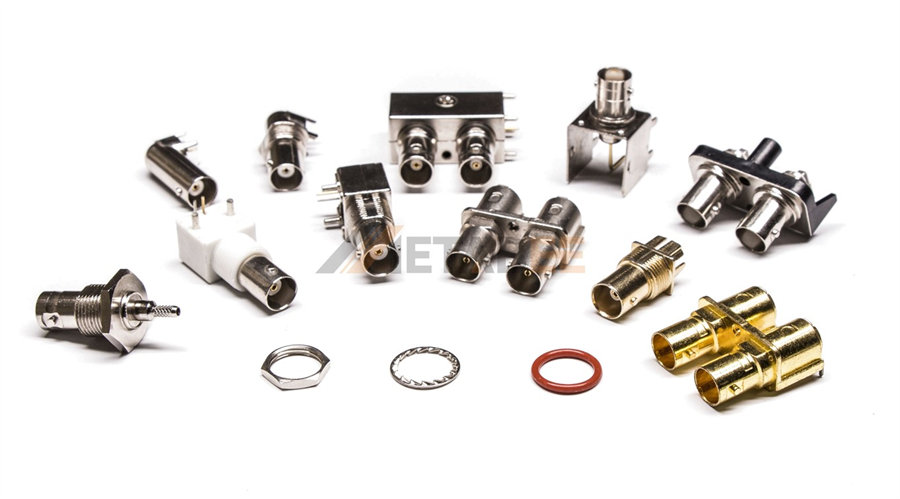
BNC connectors’ bayonet locking mechanism allows for rapid coupling, making it a favorite in laboratory environments where cables are frequently swapped. The 50 Ohm version is standard for RF test and data, while the 75 Ohm version is ubiquitous in broadcast and video infrastructure.
Related Posts:
- What is a BNC Connector? The Ultimate Guide to Types, Uses & Specifications
- BNC vs TNC Connector: Key Differences and Applications
N-Type Connectors
N-Type connectors are known for its large size, robustness, and superior power handling capabilities. The threaded coupling provides excellent mechanical stability, making it ideal for outdoor installations and large transmitting antennas.

F-Type Connectors
The F-type connector is the most cost-effective connector, using the cable’s center conductor as the connector's center pin. Its primary limitation is frequency, but its 75 Ohm impedance is perfect for television and satellite signal transmission.

UHF and Mini-UHF Connectors
The classic UHF connector (often called PL-259 (male) and SO-239 (female)) is highly reliable but suffers from non-constant impedance, limiting its use to low frequencies. The UHF Male Connector is also known as the PL259 connector, and the UHF Female Connector is also known as the SO239 connector.The Mini-UHF is a smaller, modern update used in specific vehicular applications.
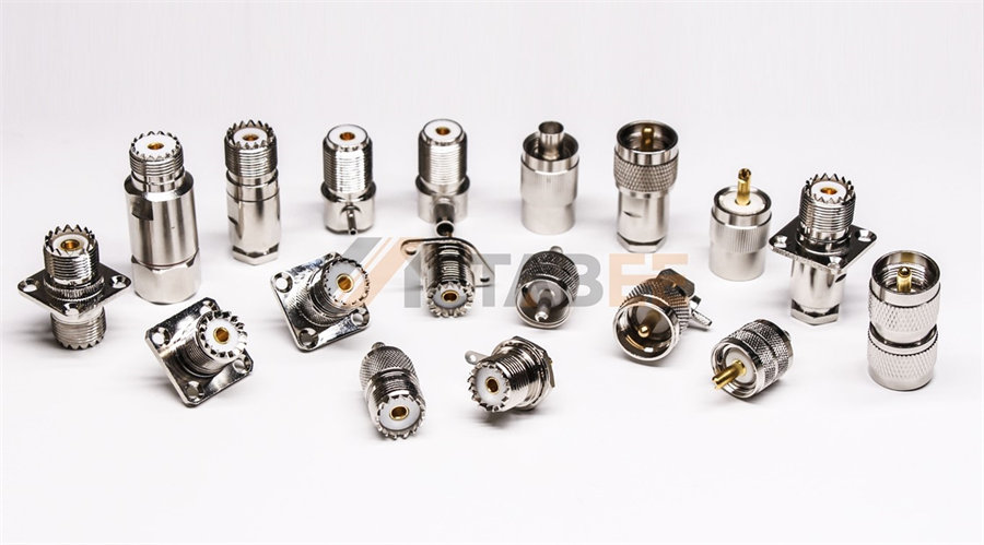
Metabee UHF (PL259 and SO239) Connectors
RF and Microwave Performance Types
These families are engineered for reliable performance in communication systems where frequency and stability are crucial.
|
Connector |
Coupling Mechanism |
Typical Impedance |
Max Frequency |
Key Applications |
|
SMA |
Threaded |
50 Ohm |
26.5 GHz |
Military, Aerospace, Commercial RF Modules |
|
TNC |
Threaded |
50 Ohm |
11 GHz |
Avionics, Radar, High-Vibration Systems |
|
SSMA |
Threaded |
50 Ohm |
38 GHz |
Dense PCB Designs, Phased Array Systems |
SMA (Sub-Miniature version A) Connectors
The SMA connector is the most commonly used small threaded connector in the world. It provides excellent repeatable performance up to 18GHz (standard grade) and 26.5GHz (precision grade). It is the default choice for military, aerospace, and commercial RF modules due to its excellent combination of size, stability, and cost-effectiveness.

Related Post:
- Beyond the Basics: Everything You Need to Know About SMA Connectors
- SMA vs RP-SMA: Key Differences, Compatibility & How to Choose the Right Connector
- SMA vs BNC: 7 Key Differences You Need to Know
TNC (Threaded Neill–Concelman) Connectors
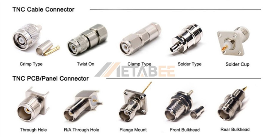
The TNC connector is essentially a threaded version of the BNC. The threaded interface dramatically improves performance in high-vibration scenarios compared to the bayonet lock. It’s frequently used in avionics, radar, and external wireless equipment where mechanical stress is a concern.
SSMA (Sub-SubMiniature version A) Connectors
The SSMA connector is a smaller, higher-frequency version of the SMA. Its compact footprint is utilized in dense printed circuit board (PCB) designs and phased array systems where space is at a premium and high-frequency performance is required, extending up to 38GHz.

Miniature, Sub-Miniature & Push-On Types
This category prioritizes high density and quick assembly, often at the expense of maximum frequency or power handling.
|
Connector |
Coupling Mechanism |
Max Frequency |
Key Applications |
|
SMB |
Snap-on |
4 GHz |
Automotive, Telecom Equipment, Quick-disconnect lab hookups. |
|
SSMB |
Snap-on |
10 GHz |
High-density equipment, internal interconnects. |
|
MCX / MMCX |
Snap-on |
6 GHz |
GPS, WiFi Modules, IoT Antennas, Hearing Aids (MMCX). |
|
DIN 1.0/2.3 |
Push-Pull/Snap-on |
10 GHz |
High-density Broadcast Video, Digital Coax (E3/DS3). |
SMB (Sub-Miniature version B) & SSMB Connectors
The SMB is a push-on connector perfect for applications requiring frequent connections where space is limited and speed is prioritized over secure threading. The SSMB offers similar functionality but in an even smaller form factor for greater density.

Metabee SMB and SSMB Connectors
MCX (Micro-Miniature Coaxial) & MMCX Connectors
The MCX and MMCX connectors are among the smallest push-on connectors, ideal for low-profile applications in handheld and portable wireless devices. The MMCX is particularly popular for connecting tiny internal antennas to Wi-Fi/Bluetooth modules.

Metabee MCX and MMCX Connectors
DIN 1.0/2.3 Connectors
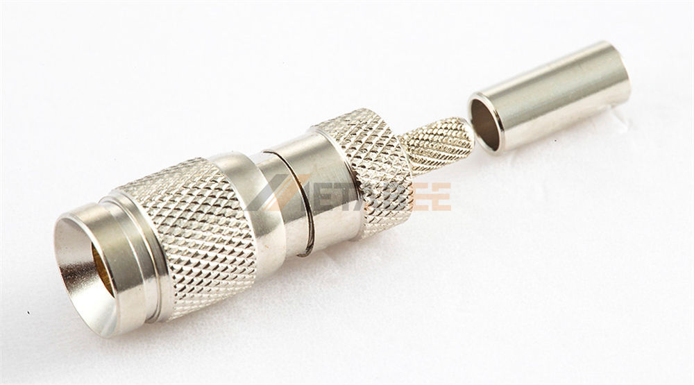
The compact DIN 1.0/2.3 connector is used extensively in high-density telecommunications racks and broadcast equipment because of its small size and reliable push-pull locking mechanism. However, it should not be confused with the physically large 7/16 DIN.
Metabee DIN 1.0/2.3 Connectors
Precision and Millimeter-Wave Series
These connectors represent the pinnacle of RF connector technology, designed to handle frequencies associated with 5G, advanced radar, and next-generation satellite communications. They demand extremely tight manufacturing tolerances.
|
Connector |
Coupling Mechanism |
Typical Impedance |
Max Frequency |
Key Applications |
|
Precision (2.92mm 'K', 2.4mm, 1.85mm 'V', 1.0mm) |
Threaded |
50 Ohm |
Up to 110 GHz (1.0mm) |
Test & Measurement (VNA), Advanced Radar, Space, 5G |
|
7/16 DIN |
Threaded (Large) |
50 Ohm |
7.5 GHz |
High-Power Base Station Antennas, Low PIM Telecom |
|
U.FL/IPEX |
Snap-on (Friction) |
50 Ohm |
6 GHz |
IoT Devices, Laptops, GPS/WiFi Modules (Board-to-Antenna) |
- High-Frequency Precision Connectors (2.92mm 'K', 2.4mm, 1.85mm 'V', 1.0mm): These families are dimensionally compatible across manufacturers, enabling intermateability across vast frequency ranges 40GHz up to 110GHz. They are the foundation of high-speed test and measurement equipment (VNA calibration kits), military sensor arrays, and space-based platforms. The 1.0mm connector is currently the standard for the highest commercial frequencies.
- 7/16 DIN: A large, specialized connector known for its exceptional PIM (Passive Intermodulation) performance and power handling. It is the primary connector used at the junction between high-power cellular transmitters and base station antennas.
- U.FL/IPEX (Hirose U.FL / I-PEX MHF): These are tiny, board-level connectors used to link the RF output of a circuit board to an external antenna or pigtail. They are optimized for extremely low-profile mounting in IoT devices, laptops, and smart home technology.
Coaxial Connector Selection Guide: How to Choose the Right Type
Selecting the correct coaxial connector is crucial to system performance and cost efficiency. A mistake here can lead to excessive signal loss, system failure, and unnecessary expenses.
Key Selection Criteria
1. Operating Frequency: This is the most important electrical criterion. The chosen connector’s cut-off frequency must be significantly higher than the maximum frequency of the signal being transmitted. For example, using a BNC (4 GHz) in a 10GHz application is guaranteed to cause severe signal degradation.
2. Impedance (50 Ohm vs. 75 Ohm): The connector impedance must exactly match the system impedance. 50 Ohm is the standard for RF transmission (wireless, data, military), while 75 Ohm is the standard for video and CATV (Cable TV). Never mix the two.
3. Power Handling: For high-power transmitters (e.g., base stations), large connectors like the N-Type or 7/16 DIN are required. Power handling capacity is affected by the size of the center pin and the quality of the dielectric material.
4. Environmental Factors:
- Temperature: Connectors must tolerate the operational temperature range.
- Sealing/Ingress Protection (IP Rating): For outdoor use (e.g., antennas), connectors require high IP ratings (e.g., IP67) to resist dust and moisture.
- Vibration and Shock: Threaded connectors (TNC, SMA) are superior to bayonet or push-on types in high-vibration environments (e.g., automotive, aerospace).
5. Cost and Size Constraints: Space-constrained applications (IoT, handheld devices) demand miniature connectors (MMCX, U.FL), while budget-sensitive projects (CATV) rely on cost-effective F-Type.
Common Mismatches to Avoid
- Ignoring the Frequency Limit: This is the most common and costly mistake. Always check the manufacturer's data sheet for the specified maximum operational frequency.
- Impedance Mismatch: As discussed, mixing 50 Ohm and 75 Ohm components results in reflections, causing signal degradation and power loss.
- Inadequate IP Rating: Using indoor-rated connectors for external applications will lead to corrosion and system failure due to environmental damage.
- Over-Tightening Threaded Connectors: This can damage the internal structure, especially the fragile center pin and dielectric of precision connectors, leading to performance drift and failure.
RF Adapters: Bridging the Signal Gap
RF adapters are indispensable tools, particularly in laboratory testing, prototyping, and integrating components from different systems. They act as bridges, allowing connection between two dissimilar coaxial interfaces.
Definition and Purpose
An RF adapter is a connector with different interface types or genders on its two ends. Their primary purpose is to:
- Interface Compatibility: Connect a device with an N-Type port to a cable with an SMA plug.
- Gender Change: Convert a male plug to a female jack, or vice versa (e.g., SMA Male to SMA Male).
- Tee and Bulkhead Use: Provide specialized mechanical functions (e.g., panel mounting or signal splitting).
Adapter Types and Configurations
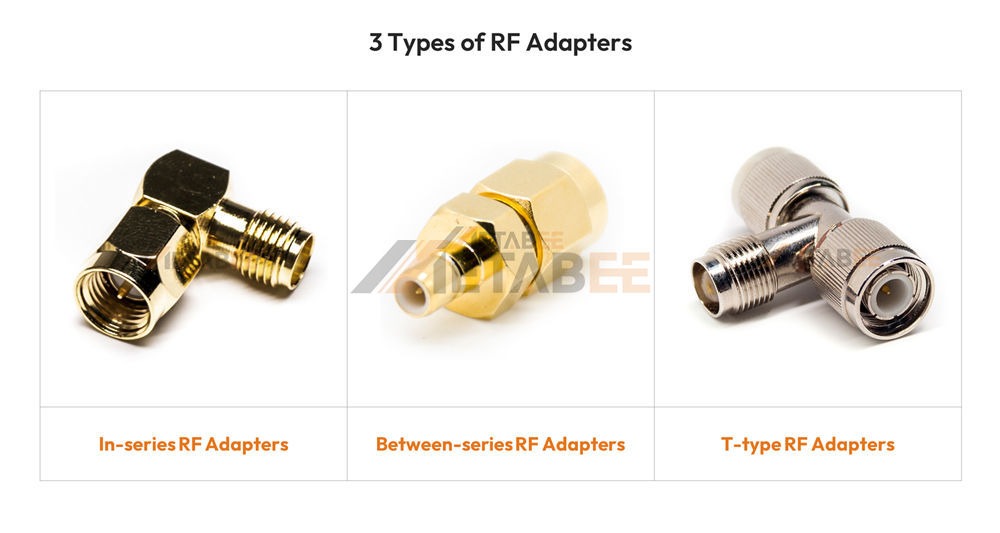
- In-series Adapters: Connect two plugs or two jacks of the same connector type (e.g., BNC Male to BNC Male, or N-Type Bulkhead Jack). These are often used as gender changers or extenders.
- Between-series Adapters: These are the most common type, connecting two different connector families (e.g., SMA Male to N-Type Female). They are essential for test setups where high-frequency cables (often SMA) must interface with larger bench equipment (often N-Type).
- T-Adapters and Cross-Series Adapters: T-Adapters are used to split or combine signals (introducing some loss). Cross-series adapters link three or more different interfaces, though their use is minimized in permanent installations due to performance degradation.
Performance Considerations
While adapters are necessary, every connection point introduces a slight degradation in the signal. When choosing an adapter, one must consider:
- Insertion Loss: The power lost as the signal passes through the adapter. High-quality, precise adapters minimize this loss.
- VSWR/Return Loss: Poorly designed adapters will cause impedance mismatches, leading to signal reflection. Precision-grade adapters (e.g., those specified up to 40GHz) utilize precision internal construction to minimize this effect.
- Mechanical Integrity: Adapters, especially in high-torque environments, must be robust and maintain secure contact.
Key Applications
The primary applications for RF adapters include:
- Test and Measurement Labs: Where flexibility is crucial for connecting various pieces of equipment and different cable types.
- Prototyping: Quickly integrating disparate components during the development phase.
- Temporary System Integration: Field testing or temporary network links where dissimilar equipment must communicate.
Major Manufacturers of Coax Connectors
The market for coaxial connectors is dominated by companies that specialize in high-precision manufacturing, material science, and stringent quality control standards. When sourcing connectors, quality is non-negotiable, as even a minor defect can severely compromise signal performance.
Industry Leaders
Globally, several large multinational corporations set the pace for innovation and mass production, including:
- Amphenol: One of the largest, with an extensive portfolio spanning every conceivable connector type from legacy BNC to millimeter-wave precision interfaces.
- TE Connectivity (TE): Known for robust solutions in automotive, aerospace, and defense applications.
- Huber+Suhner: A Swiss specialist recognized for high-quality, high-frequency, and low PIM solutions, especially in the telecom sector.
- Rosenberger: Highly regarded for precision microwave connectors and robust automotive interfaces.
Metabee: Your High-Performance Coax Partner
Metabee distinguishes itself in the global supply chain by focusing on high-reliability solutions at a competitive scale, providing the quality assurance required by major manufacturers without the inflated overhead of larger brands.
- Metabee’s Specialization: Metabee excels in the mass production of high-demand connectors, particularly SMA, BNC, N-Type, and the popular miniature series (MCX/MMCX). Their manufacturing processes are designed to meet stringent IEC and MIL-STD dimensional tolerances, ensuring seamless intermateability with other global brands.
- Commitment to Performance: Recognizing the shift to higher frequencies, Metabee invests heavily in quality control, using modern Vector Network Analyzers (VNAs) to certify that their connectors—especially those designated for microwave applications—meet or exceed published Return Loss and Insertion Loss specifications.
- Competitive Advantage: For foreign trade buyers and OEMs, partnering with Metabee means accessing top-tier performance and reliability that is essential for export, while benefiting from the cost efficiency needed to maintain competitive market pricing.
To learn how Metabee can be your reliable source for high-performance coaxial connectors and custom cable assemblies, contact our sales team today for a comprehensive quote and technical consultation.
Conclusion
The world of coaxial connectors is diverse and complex, yet governed by fundamental principles of physics and standardization. The ultimate performance of your electronic system—from your laboratory VNA to the 5G tower—rests on the quality and correct selection of these components.
The connector’s primary job is to maintain impedance matching to prevent signal reflection.
- Frequency dictates size: Higher frequencies demand smaller, precision-tolerance connectors.
- Coupling mechanism determines durability and speed: Threaded for stability, bayonet/snap-on for speed.
- Selection must be rigorous, factoring in frequency, impedance, power handling, and environmental requirements.
Whether you are designing a new satellite system, upgrading a broadcast facility, or simply seeking high-reliability components for your product line, the choice of a coax connector is too important to leave to chance.
Don't compromise your system's performance with subpar components. Contact the experts at Metabee today. We specialize in providing the precise, high-frequency connectors and adapters you need, backed by guaranteed quality and exceptional foreign trade service.
Coaxial Connector Frequently Asked Questions (FAQ)
Q: What is the primary function of a coaxial connector in an RF system?
A: The core function is to establish a secure, low-loss connection while maintaining the cable's characteristic impedance (typically 50 Ohm or 75 Ohm) throughout the junction to prevent signal reflection.
Q: What is the key difference between 50 Ohm and 75 Ohm impedance?
A: 50 Ohm is the industry standard for general RF transmission (wireless, data, military), while 75 Ohm is the standard for video and CATV (Cable TV) applications. You should never mix the two.
Q: What happens if there is an impedance mismatch in the connection?
A: If the impedance match is not maintained, part of the high-frequency signal will reflect back towards the source, a phenomenon known as Return Loss or high VSWR (Voltage Standing Wave Ratio), leading to reduced signal strength and system instability.
Q: Why must connector sizes decrease as the operating frequency increases?
A: As the signal frequency increases (especially into the microwave and millimeter-wave spectrum), the physical size of the connector must decrease to minimize unwanted modes of transmission (modal interference) and leakage.
Q: Which coupling mechanism offers the best mechanical stability and vibration resistance?
A: Threaded coupling mechanisms (e.g., N-Type, SMA, TNC) provide superior mechanical stability and are ideal for high-vibration environments, unlike bayonet (BNC) or push-on types.
Q: What is the most common and costly mistake to avoid when selecting a coax connector?
A: Ignoring the Frequency Limit. The chosen connector’s cut-off frequency must be significantly higher than the maximum frequency of the signal being transmitted to avoid severe signal degradation.
Q: Which connector family is considered the workhorse of modern wireless devices, offering a balance of size, frequency, and cost?
A: The SMA (SubMiniature version A) connector is the most commonly used small threaded connector, providing excellent repeatable performance up to 26.5 GHz (precision grade) for military, aerospace, and commercial RF modules.
Q: What are the two primary applications for the large, robust N-Type and 7/16 DIN connectors?
A: They are used for high-power, low-frequency applications. The N-Type is known for high-power handling, and the 7/16 DIN is specialized for High-Power Base Station Antennas due to its exceptional Low PIM (Passive Intermodulation) performance.
Q: What are precision connectors (like 2.92mm, 2.4mm, 1.0mm) designed for?
A: They are designed for the millimeter-wave regime, handling frequencies up to 110 GHz, and are the foundation of high-speed Test & Measurement equipment (VNA) and advanced 5G/Radar systems.
Q: What are the key standards that govern the dimensional and electrical performance of popular connectors?
A: The most important standards are the MIL-STD series (specifically MIL-C-39012 and MIL-STD-348 for defense and aerospace) and the IEC 61169 series for commercial and industrial requirements.
