
In RF, broadcast video, and telecommunications, BNC connectors are widely used for their secure and convenient bayonet coupling design. However, choosing between 50 Ohm and 75 Ohm BNC connectors is critical, as the wrong impedance can affect signal performance.
This guide explains the key differences between 50 Ohm and 75 Ohm BNC connectors, including their construction, signal characteristics, and typical applications, helping you choose the right option for your project.
Introduction
Before diving into the direct comparisons, it is essential to establish a baseline understanding of what these ratings mean and the underlying physics that govern them.
BNC (Bayonet Neill-Concelman) connectors are coaxial connectors that use a bayonet locking mechanism for quick and secure connections. They are widely used in RF, test and measurement, video, and broadcast systems.
BNC connectors are available in both 50 Ohm and 75 Ohm configurations, and these ratings are not arbitrary—they reflect different engineering requirements for power handling, signal transmission, and attenuation.

What 50 Ohm and 75 Ohm Means in BNC
When we refer to a "50 Ohm BNC" or a "75 Ohm BNC," we are talking about the characteristic impedance of the connector and the coaxial cable it is designed to terminate.
In the early days of RF engineering, specifically during the development of radar and telecommunications in the 1920s and 1930s, engineers discovered a fundamental trade-off in coaxial cable design. They found that a coaxial cable optimized for maximum power handling (crucial for radio transmitters) had an ideal characteristic impedance of around 30 Ohms. Conversely, a cable optimized for the lowest possible signal loss (attenuation) had an ideal impedance of around 77 Ohms.
- 50 Ohm: The 50 Ohm standard was chosen as the perfect compromise between high power handling and low signal loss. It has since become the default standard for almost all RF, microwave, and data transmission applications.
- 75 Ohm: The 75 Ohm standard (rounding down slightly from 77 Ohms for convenience) was adopted for applications where signal loss is the primary concern, and high power handling is irrelevant. This makes it the undisputed standard for receiving antennas, broadcast video, and audio applications.
A BNC connector must match the impedance of the cable and the equipment it connects to. A 50 Ohm BNC connector is engineered to maintain a 50 Ohm electrical pathway, while a 75 Ohm connector maintains a 75 Ohm pathway.
The Definition of Impedance
To understand the difference between 50 Ohm and 75 Ohm BNC connectors, it is important to first understand impedance. Unlike simple DC resistance, which can be measured with a standard multimeter, impedance describes how a circuit or component opposes the flow of alternating current (AC) or RF signals.
In transmission lines such as coaxial cables, characteristic impedance, denoted as Z0, is the voltage-to-current ratio of a traveling wave along the transmission line. It is primarily determined by the line's physical geometry and the dielectric material between the conductors.
For a coaxial cable, the characteristic impedance can be approximated by:
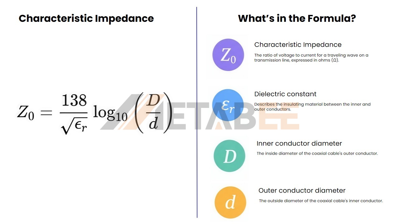
Because characteristic impedance depends on the physical geometry and dielectric properties of a transmission line, 50 Ohm and 75 Ohm BNC connectors are designed with different internal dimensions and dielectric configurations to achieve their respective impedance characteristics.
50 Ohm vs 75 Ohm BNC Connectors: Key Differences
While the cables do the heavy lifting of carrying the signal, the BNC connectors serve as the critical bridge. An incorrectly matched connector will alter the D/d ratio mentioned above, creating an impedance "bump" that reflects the signal back toward the source.

Quick Comparison
|
Feature |
50 ohm BNC Connector |
75 ohm BNC Connector |
|
Impedance |
50Ω |
75Ω |
|
Center Contact |
Typically larger center-contact geometry |
Typically smaller or optimized center-contact geometry |
|
Dielectric/Internal Geometry |
More dielectric material may be present at the mating interface |
Reduced or absent dielectric at the mating interface in many designs |
|
Electrical Performance |
Optimized for 50 Ω systems and RF transmission |
Optimized for 75 Ω systems and video/data transmission |
|
Typical Applications |
RF, test &measurement, instrumentation |
Broadcast video, SDI, CCTV, telecom |
Construction
The most reliable way to tell a standard 50 Ohm BNC from a 75 Ohm BNC by eye is to look at the mating interface (the end you plug into the female jack).
- 50 Ohm BNC Construction: Because 50 Ohms requires a lower impedance, the ratio between the outer and inner conductor must be smaller. To achieve this while keeping the outer shell standard, 50 Ohm connectors utilize a solid dielectric material—typically PTFE (Teflon) or Delrin—that completely fills the space between the center pin and the outer shielding up to the mating edge. When you look inside a 50 Ohm BNC, you will see a solid ring of white plastic surrounding the center pin.
- 75 Ohm BNC Construction: To achieve a higher impedance of 75 Ohms, the ratio between the conductors must be larger, or the dielectric constant must be lower. Since the outer shell is fixed by the BNC mechanical standard, engineers achieve 75 Ohms by removing the dielectric material from the mating interface, using air (which has a dielectric constant of ~1) as the insulator. When you look inside a standard 75 Ohm BNC connector, you will typically see an air gap (empty space) surrounding the center pin. Note: Some modern, high-end 12G-SDI 75 Ohm connectors use specialized low-density Teflon and may look similar to 50 Ohm, so part numbers should always be verified.
Performance
The performance difference between the two connectors is characterized by how they handle different types of electrical loads.
- 50 Ohm Performance: These connectors are rugged and designed to handle significant wattage. When used in a 50 Ohm system, they provide a very low Voltage Standing Wave Ratio (VSWR), meaning almost all the power is transmitted forward, and very little is reflected back. They maintain this excellent VSWR up to 4 GHz in standard commercial grades, making them perfect for high-frequency RF transmission.
- 75 Ohm Performance: These connectors are optimized for signal fidelity rather than power. They are engineered to pass delicate, complex waveforms (like high-definition video signals) with minimal attenuation. In a 75 Ohm system, a 75 Ohm connector virtually eliminates return loss, preventing "ghosting" in analog video or bit-errors in digital video (SDI/HD-SDI). Specialized 75 Ohm BNCs are now precision-machined to handle 4K and 8K video over 12G-SDI at frequencies up to 12 GHz.
Applications
Because of their unique performance profiles, the two connectors have segmented the BNC market into two distinct worlds.
50 Ohm Applications:
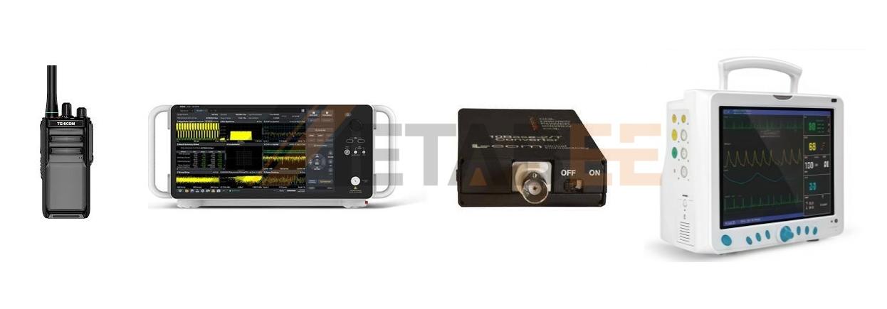
- Radio Frequency (RF): Two-way radios, amateur radio, avionics, and military communication systems.
- Test and Measurement: Oscilloscopes, signal generators, spectrum analyzers, and network analyzers rely exclusively on 50 Ohm BNCs.
- Legacy Data Networks: Old 10BASE2 "Thinnet" Ethernet networks used 50 Ohm BNCs and RG58 cables.
- Medical Equipment: Various high-power diagnostic and surgical machines.
75 Ohm Applications:
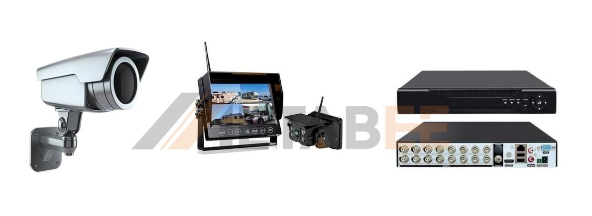
- Broadcast and Professional Video: Serial Digital Interface (SDI), HD-SDI, 3G-SDI, 6G-SDI, and 12G-SDI for cameras, switchers, and monitors.
- CCTV and Security: Analog security cameras and DVRs.
- Telecommunications: DS3/T3 central office telecommunications lines.
- Consumer Audio/Video: SPDIF digital audio and composite/component video routing.
50 Ohm vs 75 Ohm BNC Cables: Key Differences
While connectors serve as the endpoints, the coaxial cables carry the signal over distance. The distinction between 50 Ohm and 75 Ohm coaxial cables is much more pronounced than the connectors and has a massive impact on the success of your installation.
Quick Comparison
|
Features |
50 Ohm BNC Coaxial Cable |
75 Ohm BNC Coaxial Cable |
|
Impedance |
50Ω |
75Ω |
|
Common cable types |
RG58, RG174, RG213, RG316, LMR-400 |
RG59, RG6, RG11, RG179 |
|
Signal Performance |
Generally suited to higher-power RF transmission and test applications |
Generally suited to low-loss transmission of video and other high-frequency signals |
|
Typical Applications |
RF, wireless, test & measurement, communication systems |
Broadcast video, CCTV, CATV, video distribution |
Impedance
Just like the connectors, the cables derive their impedance from their physical geometry. A coaxial cable is a waveguide consisting of an inner conductor, a dielectric insulator, a woven or foil metallic shield, and an outer jacket. The distance between the inner conductor and the shield, along with the material of the dielectric (such as solid polyethylene or foam FEP), dictates the 50 or 75 Ohm characteristic.
If a cable is crushed, kinked, or bent beyond its minimum bend radius, the distance between the center conductor and the shield changes. This physical deformation instantly alters the impedance at that specific point, causing a signal reflection regardless of whether it is a 50 or 75 Ohm cable.
Cable Construction
- 50 Ohm Cable Construction: To achieve a 50 Ohm rating, the center conductor must be relatively thick compared to the overall diameter of the cable. For example, a standard RG58 50 Ohm cable has a fairly robust center wire surrounded by solid polyethylene. Because of the thicker center conductor, 50 Ohm cables are highly efficient at carrying large currents and high-wattage RF signals without melting or experiencing dielectric breakdown.
- 75 Ohm Cable Construction: To hit the 75 Ohm target, which minimizes signal loss, the center conductor is notably thinner relative to the overall diameter of the cable. In a cable like RG6 or RG59, you will find a small, stiff center wire (often copper-clad steel in cheaper cables, or solid bare copper in broadcast grades) surrounded by a thick, often foamed dielectric material. The thicker dielectric spacing reduces capacitance, which directly lowers high-frequency signal attenuation.
Signal Loss and Transmission Performance
The defining metric for cable performance is attenuation (loss), typically measured in decibels (dB) per 100 feet or 100 meters at a specific frequency.
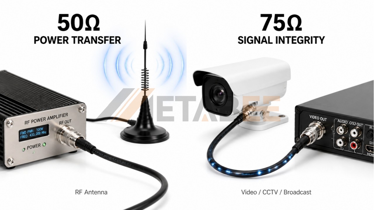
- 50 Ohm Transmission: 50 Ohm cables prioritize power transfer. While they have slightly higher attenuation per foot compared to 75 Ohm cables of the same overall thickness, they can handle the high voltage and current generated by RF amplifiers. When connecting an antenna to a 100-watt radio transmitter, a 50 Ohm cable (like RG8) is required; a 75 Ohm cable would risk dielectric failure and severe transmitter damage due to impedance mismatch.
- 75 Ohm Transmission: 75 Ohm cables prioritize signal integrity. A security camera or a broadcast video router generates a very weak, low-voltage signal (usually 1 volt peak-to-peak). The primary enemy of this signal is distance. 75 Ohm cables, with their low capacitance geometry, allow these delicate, high-bandwidth signals to travel much further before degrading. This is why broadband internet (cable modems) and television distribution exclusively use 75 Ohm RG6 and RG11 infrastructure.
Can 50 Ohm and 75 Ohm BNC Cables Be Used Together?
No, you should never intentionally mix them.
While they fit together, mating a 50 Ohm component with a 75 Ohm component creates an impedance mismatch. This mismatch violates the fundamental rule of transmission line theory, which states that for maximum power transfer and zero signal reflection, the source impedance, transmission line impedance, and load impedance must all be identical.
Here is what happens when you mix them:
- Signal Reflection and VSWR: When a signal traveling down a 75 Ohm cable suddenly hits a 50 Ohm connector, the change in impedance acts like a literal wall in the cable. A portion of the signal's energy bounces off this wall and reflects back toward the source. This creates a Voltage Standing Wave Ratio (VSWR) anomaly.
- Video Degradation (Return Loss): In 75 Ohm video applications, this reflection is called Return Loss. For analog video, the reflected signal bounces back and forth, arriving at the monitor slightly delayed, causing a visual "ghosting" or shadowing effect on the screen. In digital HD-SDI video, the reflections scramble the digital eye pattern, causing "cliff effect" signal dropouts, pixelation, or a complete loss of the video feed.
- Transmitter Damage: In 50 Ohm RF applications, connecting a 75 Ohm cable or antenna to a high-power 50 Ohm transmitter is highly dangerous. The mismatched impedance reflects massive amounts of RF power back into the transmitter's final amplifier stage. This reflected power generates extreme heat and can instantly burn out the expensive power transistors in the radio.
- Mechanical Stress (Historically): In the past, 50 Ohm male BNC connectors featured a significantly thicker center pin than 75 Ohm male connectors. Forcing a fat 50 Ohm pin into a tight 75 Ohm female jack would permanently bend or splay the female contacts, ruining the jack forever. Fortunately, modern IEC standards mandate that the center pin dimensions for both 50 and 75 Ohm BNCs are identical. Therefore, physical damage is no longer a major concern with modern, high-quality BNC components—but the severe electrical consequences remain.
How to Choose?
Selecting the right BNC impedance is entirely dependent on your application, the equipment you are using, and the signals you intend to transmit. Do not guess; check the documentation of your hardware.
Choose 50 Ohm BNC Connectors and Cables If:
- You are connecting an RF transmitter, transceiver, or receiver (e.g., Ham radio, Wi-Fi antennas, cellular repeaters).
- You are setting up laboratory test equipment. Oscilloscopes invariably feature 50 Ohm BNC inputs.
- You are building or maintaining 50 Ohm telecommunications networks or legacy Ethernet.
- Your primary goal is transmitting high wattage safely.
Choose 75 Ohm BNC Connectors and Cables If:
- You are working in the broadcast, film, or AV industry (SDI, HD-SDI, 4K UHD video routers and cameras).
- You are installing analog CCTV security systems or DVRs.
- You are dealing with consumer television antennas, CATV, or satellite TV distribution (though these often use F-Type connectors, 75 Ohm BNC is used in professional head-ends).
- Your primary goal is transmitting low-voltage, high-frequency signals over long distances with minimal loss.
- The golden rule: If you are dealing with video or broadcast audio, you almost certainly need 75 Ohm. Check your camera, monitor, or router—it will specify a 75 Ohm impedance.
Still unsure which BNC product is right for you? Contact our support team. Our technical specialists are available online to provide expert guidance and help you quickly find the right solution.
Conclusion
To ensure the long-term reliability of your electronic systems, matching the correct BNC impedance to your application is crucial. While a 50 Ohm BNC connector is built to maximize power transfer for RF transmitters and test equipment, the 75 Ohm variant is designed to preserve delicate signal fidelity for high-definition broadcast video and telecommunications. Although they may physically fit together, mixing these two impedances will inevitably cause signal reflections, degraded data quality, and potential hardware damage. Always remember to perform a quick visual check of the dielectric insulator before installation to prevent costly mismatched connections.
Whether you are sourcing components for a broadcast studio, a complex telecommunications network, or a military communication array, choosing high-quality hardware is just as important as selecting the right impedance. At Metabee, we specialize in providing premium electronic components, including precision-engineered BNC connectors, robust circular and military connectors, and high-performance RJ45 and CAT series solutions. Browse our extensive catalog today to find the reliable components your next project demands, and contact our support team for customized wholesale and B2B sourcing support.
Related Products
FAQ
Q1: How can I visually tell the difference between a 50 Ohm and 75 Ohm BNC connector?
A: Look inside the connector at the center mating interface. A 50 Ohm BNC typically has a solid white plastic insulator (usually Teflon or Delrin) completely surrounding the center pin. A 75 Ohm BNC typically lacks this solid plastic, featuring an air gap (empty space) between the pin and the outer metal shell.
Q2: Can I plug a 50 Ohm BNC cable into a 75 Ohm BNC port?
A: No. Physically, they will connect perfectly because the outer locking mechanism is identical. However, electrically, you should never mix them. Doing so causes an impedance mismatch, which leads to signal reflection, data loss, and poor overall performance.
Q3: What happens if I use a 75 Ohm BNC cable for an RF radio transmitter?
A: Using a 75 Ohm component in a 50 Ohm high-power RF system is highly dangerous. The impedance mismatch will reflect massive amounts of RF power back into the transmitter. This generates extreme heat and can instantly and permanently damage your radio's internal amplifier.
Q4: Which BNC impedance is the standard for CCTV and broadcast video?
A: 75 Ohm is the undisputed standard for all video applications, including analog CCTV, SDI, HD-SDI, and modern 12G-SDI. 75 Ohm systems are designed for maximum signal fidelity and minimal attenuation over long cable runs.
Q5: Do BNC connectors have a maximum frequency limit?
A: Yes. Standard commercial 50 Ohm BNCs perform excellently up to 4 GHz, while standard 75 Ohm BNCs are optimal up to 3 GHz. However, specialized precision BNCs (such as those used for 12G-SDI video) are heavily engineered to handle frequencies up to 12 GHz.
Q6: Why do oscilloscopes and test equipment always use 50 Ohm BNCs?
A: Test equipment requires a highly consistent, low VSWR connection to measure high-frequency signals accurately without distorting them. 50 Ohms is the absolute industry standard for optimal power transfer and signal consistency in RF and microwave laboratory environments.
Q7: Can a mismatched BNC connector physically damage my female jack?
A: Historically, yes. Older 50 Ohm male pins were slightly thicker than 75 Ohm pins, meaning a 50 Ohm plug could permanently stretch a 75 Ohm female jack. However, modern IEC standards mandate that the center pin dimensions for both 50 and 75 Ohm BNCs are identical. So while physical damage is no longer a major concern, the severe electrical issues (signal reflection) remain.
