
When sourcing RF interconnects, engineers often encounter a puzzling discrepancy across manufacturer datasheets. One datasheet lists a maximum rating of DC to 6 GHz for an SMA plug. Another specifies DC to 18 GHz for a seemingly identical connector. Meanwhile, precision microwave catalogs rate the same 1/4-36 threaded interface up to 26.5 GHz or even 27 GHz.
Why does the SMA connector frequency range vary so widely across identical mechanical threads?
The standard SMA connector frequency range is DC to 18 GHz under MIL-STD-348 specifications. However, commercial crimp connectors for flexible cables operate from DC to 6 GHz, while precision passivated stainless steel SMA connectors extend the upper frequency limit to DC to 26.5 GHz.
Understanding what governs these frequency tiers prevents costly signal reflections and over-engineered bills of materials. In this guide, our RF engineering team at Metabee breaks down the physics behind the SMA max frequency. We also compare 18 GHz and 26.5 GHz materials, analyze insertion loss across frequency bands, and provide a practical selection checklist.
What Is the Standard SMA Connector Frequency Range Across Different Grades?
Not all SubMiniature version A (SMA) connectors share the same upper bandwidth ceiling. Although every standard SMA interface uses a 1/4-36 UNS-2A/2B coupling thread and a 50-Ohm characteristic impedance, internal geometry dictates high-frequency performance. In practice, the SMA connector bandwidth falls into 3 distinct engineering tiers.
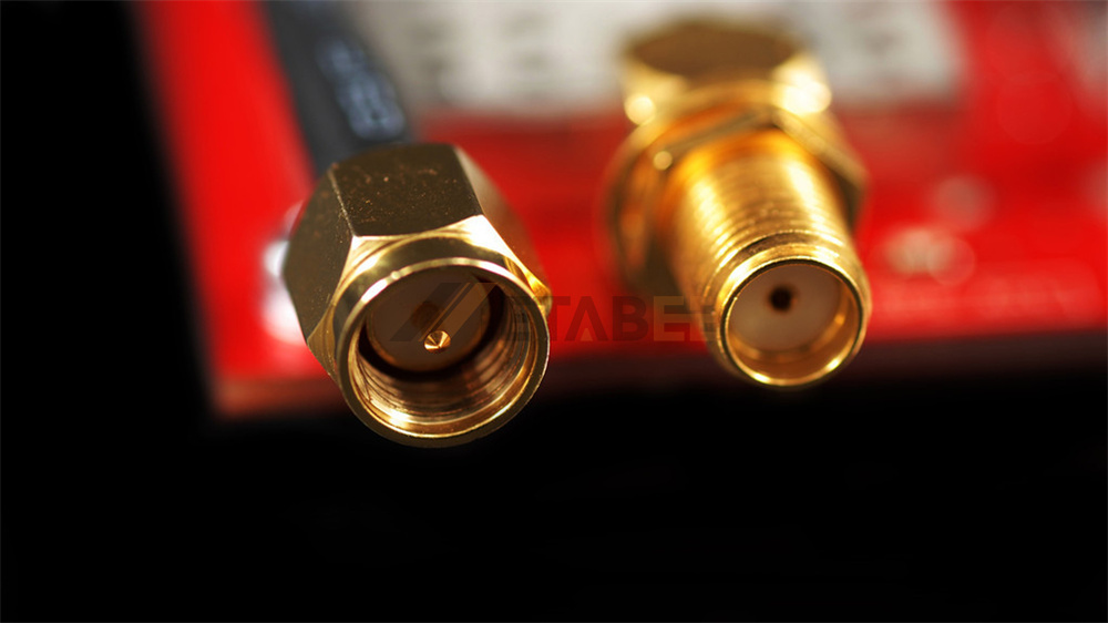
Commercial and Reverse-Polarity Tier (DC to 3 GHz / 6 GHz)
Entry-level SMA connectors and reverse-polarity RP-SMA connectors are typically rated from DC to 3 GHz or DC to 6 GHz. These models are designed for flexible braided coaxial cables such as RG174, RG316, RG58, LMR195, and LMR400.
At frequencies above 6 GHz, flexible single-braid cables suffer from RF leakage and high dielectric attenuation. Furthermore, hex-crimp ferrule transitions introduce minor impedance steps that increase return loss at microwave frequencies. Because of this, DC–6 GHz connectors are optimized for cost-effective sub-6 GHz systems. Typical applications include 2.4 GHz and 5.8 GHz Wi-Fi routers, cellular LTE antennas, IoT gateways, FPV drones, and GPS/GNSS receivers.

Standard MIL-STD-348 Microwave Tier (DC to 18 GHz)
When RF engineers ask how high frequency can SMA handle by default, the textbook answer is DC to 18 GHz. Originally developed in the 1960s and standardized under MIL-STD-348 and MIL-PRF-39012, the classic SMA connector in 18GHz systems serves as the workhorse of the microwave industry.
Standard 18 GHz SMA connectors use a solid virgin PTFE (polytetrafluoroethylene) dielectric insulator. Their bodies are machined from either gold-plated brass or passivated stainless steel. They pair seamlessly with 0.086-inch (086 Series) and 0.141-inch (141 Series) semi-rigid coaxial cables, panel-mount flanges, and microstrip PCB launches.
High-Frequency Precision Extended Tier (DC to 26.5 GHz / 27 GHz)
To support K-band radar, satellite transponders, and 5G millimeter-wave intermediate-frequency (IF) stages, manufacturers developed extended-range high frequency SMA connectors rated from DC to 26.5 GHz. Select specialized models even reach DC to 27 GHz.
Achieving clean signal transmission at 26.5 GHz requires tighter CNC machining tolerances on the outer conductor wall (thick wall SMA) and center pin. At Metabee, our 26.5 GHz SMA series utilizes passivated stainless steel bodies and dual composite PEI & PTFE or PEEK & PTFE dielectric beads. This construction keeps the Voltage Standing Wave Ratio (VSWR) at or below 1.15:1 to 1.25:1 across the entire K-band spectrum.
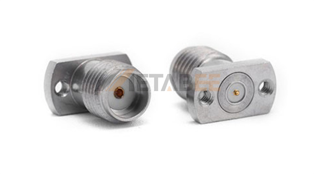
Quick Comparison: SMA Frequency Tiers and Representative Models
|
Frequency Tier |
Typical Body Material |
Dielectric Material |
Typical Max VSWR |
Primary Applications |
|
DC – 6 GHz |
Gold/Nickel-Plated Brass |
Virgin PTFE |
≤ 1.25:1 – 1.30:1 |
Wi-Fi, Sub-6G 5G, IoT, RG316/LMR Jumpers |
|
DC – 18 GHz |
Gold-Plated Brass / Stainless Steel |
Virgin PTFE |
≤ 1.15:1 – 1.25:1 |
Ku-Band Comms, SDR Boards, RF Filters |
|
DC – 26.5 GHz |
Passivated Stainless Steel |
Dual PEI & PTFE / PEEK & PTFE |
≤ 1.15:1 – 1.25:1 |
K-Band Radar, Satellite, VNA Test Sets |
Not sure whether your RF module requires a standard 18 GHz brass connector or a 26.5 GHz stainless steel launcher? Contact the Metabee engineering team today for free sample evaluation and datasheet matching.
What Determines the SMA Connector Frequency Limit? The Physics of Cutoff Frequency
Why does the SMA connector frequency limit stop around 26.5 GHz instead of continuing indefinitely? The ceiling is set by electromagnetic waveguide physics, dielectric stability, and mechanical concentricity.
TEM Propagation vs. Higher-Order TE11 Mode Cutoff
Beginners often ask at what frequency does SMA cable considered transmission line in circuit design. In RF engineering, any interconnect acts as a transmission line once its physical length exceeds one-tenth of the signal wavelength (λ/10). At 10 GHz in PTFE, λ/10 is just 2.1 millimeters, meaning the connector body itself is a critical transmission line.
Coaxial connectors are engineered to carry signals purely in the Transverse Electromagnetic (TEM) mode. In TEM mode, both electric and magnetic fields remain perpendicular to the direction of propagation. However, at higher frequencies, the signal wavelength shrinks enough to fit around the dielectric circumference. At that point, the first higher-order waveguide mode (TE₁₁) begins to propagate.
The theoretical TE₁₁ cutoff frequency (f_c) of a coaxial line is governed by its inner shield diameter (D), center conductor diameter (d), and dielectric constant (εᵣ).
Coaxial TE₁₁ Mode Cutoff Frequency Formula:

In a standard 50-Ohm SMA interface:
- The outer conductor inner diameter (D) is 4.13 mm (0.1625 inches).
- The center contact diameter (d) is 1.27 mm (0.050 inches).
- The solid PTFE dielectric constant (εᵣ) is approximately 2.04.
Plugging these dimensions into the equation yields a theoretical TE₁₁ cutoff frequency between 31 GHz and 34 GHz. Once TE₁₁ propagation starts, it travels at a different velocity than the TEM mode. This velocity mismatch causes severe phase distortion and sharp insertion loss spikes. Engineering standards apply a safety margin below this resonance threshold, establishing 26.5 GHz as the reliable mode-free upper limit.
Dielectric Stability: Virgin PTFE vs. Composite PEI & PTFE
When evaluating 18GHz vs 26.5GHz SMA connectors, the dielectric insulator is one of the most overlooked differentiators. Standard 18 GHz connectors rely on a single sleeve of virgin PTFE. While PTFE offers a low dissipation factor, it exhibits a thermal expansion trait near room temperature. Engineers refer to this phenomenon as cold flow or the PTFE phase transition.
During thermal cycling from -55°C to +165°C, pure PTFE can expand axially and protrude slightly beyond the mating reference plane. At 6 GHz, a 0.05 mm dielectric shift is negligible. At 26.5 GHz, that same shift creates a capacitive impedance mismatch that degrades return loss.
To solve this, Metabee designs its DC–26.5 GHz precision receptacles with a dual PEI & PTFE or PEEK & PTFE dielectric structure. The rigid polyetherimide (PEI) or PEEK captivation bead locks the center contact in place mechanically, while the PTFE section preserves low dielectric loss.
Body Metallurgy and Mating Torque: Brass vs. Stainless Steel
Body hardness directly affects high-frequency repeatability. Gold-plated brass is machinable and cost-effective, making it the preferred choice for DC–6 GHz and DC–18 GHz commercial production. However, brass is a relatively soft alloy with a recommended mating torque of only 3 to 5 in-lbs. Over-tightening a brass coupling nut can deform the mating shoulder and alter the air gap at the interface.
Precision 26.5 GHz SMA connectors use passivated stainless steel housings rated for 7 to 10 in-lbs (typically calibrated at 8 in-lbs). Stainless steel resists thread wear across more than 500 mating cycles and maintains sub-micron reference-plane flatness under heavy vibration.

How Termination Style and Cable Pairing Impact Practical SMA Bandwidth
Even if you select a 26.5 GHz connector interface, the rear termination can bottleneck your system bandwidth. Both cable architecture and PCB launch geometry must match your target operating frequency.
Coaxial Cable Connectors: Semi-Rigid (086 / 141) vs. Flexible (RG316 / LMR)
For full 18 GHz to 26.5 GHz performance, engineers pair SMA plugs with semi-rigid or hand-formable coaxial cables like the 047 Series, 086 Series (RG405), and 141 Series (RG402). The solid copper outer jacket of a semi-rigid cable solders 360 degrees around the connector body, providing 100% RF shielding. Conversely, flexible braided cables (RG174, RG316, LMR200) should be restricted to applications below 6 GHz or 12.4 GHz.

PCB Mount Connectors: Through-Hole vs. High-Frequency Edge Launch
Standard vertical through-hole SMA jacks (with a 5.08 mm or 6.35 mm square footprint) work well up to 6 GHz or 12 GHz. Above that frequency, the 90-degree transition from a vertical pin into a horizontal PCB trace acts as a parasitic inductor. Any uncompensated pin stub extending through the bottom of the board further acts as a resonant stub filter.
To achieve clean PCB transitions up to 26.5 GHz, designers specify a high frequency SMA end launch connector or a solderless compression connector:
- Custom-Slotted Edge Launch: The signal pin launches in-line with the 50-Ohm microstrip or grounded coplanar waveguide (GCPW) trace. Matching the connector slot width to the exact PCB thickness (0.8mm, 1.2mm, 1.6mm, or 1.9mm) minimizes step capacitance.
- Solderless Compression Mount: A precision cylindrical contact (Ø0.51mm) compresses directly onto a surface pad using mounting screws. Eliminating solder fillets removes variable parasitic capacitance on millimeter-wave evaluation boards.
Field-Replaceable Glass-Bead and Flat-Tab Panel Launchers
In hermetically sealed aerospace radar and satellite amplifier housings, opening a welded cavity to repair a worn external port is impractical. Two specialized flange designs preserve 26.5 GHz bandwidth across enclosure walls:
- Field-Replaceable Socket Receptacles: These connectors feature a precision rear socket for 0.23mm to 0.51mm pins. The flange body slides directly over a Kovar glass-to-metal hermetic feedthrough pin. Technicians can swap damaged external connectors in the field without disturbing internal seals.
- Flat-Tab Launch Receptacles: These models feature a 0.8mm Flat Pin Contact instead of a round pin. The flat tab sits flush on microstrip traces to minimize launch inductance up to 26.5 GHz.
Designing a custom PCB layout or sealed RF housing? Reach out to Metabee for 3D STEP models, footprint drawings, and tailored PCB launch recommendations.
Understanding SMA Connector Loss vs. Frequency and VSWR Degradation
When budgeting link margins, engineers must account for SMA connector loss vs frequency. Both insertion loss (attenuation) and return loss degrade predictably as frequency increases.
Insertion Loss vs. Frequency (√f Scaling Law)
Total insertion loss vs frequency in a coaxial connector is the sum of skin-effect conductor loss (which scales with √f) and dielectric absorption loss (which scales linearly with f). Up to 26.5 GHz, conductor loss dominates.
Industry standards express maximum SMA insertion loss in decibels (dB) as a function of frequency in GHz:
- Precision Straight SMA (DC–26.5 GHz): IL ≤ 0.03√f(GHz) to 0.06√f(GHz) dB
- Standard Straight SMA (DC–18 GHz): IL ≤ 0.05√f(GHz) to 0.08√f(GHz) dB
- Right-Angle SMA: IL ≤ 0.08√f(GHz) to 0.15√f(GHz) dB
For example, a precision Metabee straight receptacle rated at ≤ 0.04√f dB introduces very low attenuation. It adds less than 0.08 dB at 4 GHz, 0.17 dB at 18 GHz, and 0.21 dB at 26.5 GHz.
Return Loss and VSWR Across Frequency Bands
VSWR measures how much RF power reflects back toward the source due to impedance discontinuities. A connector rated at ≤1.15:1 VSWR (23.1 dB return loss) up to 18 GHz typically reaches ≤1.25:1 VSWR at 26.5 GHz. In multi-port test setups where signals pass through six or eight connectors in series, choosing low-VSWR 26.5 GHz interfaces prevents cumulative standing-wave ripple.
Beyond 26.5 GHz: Can SMA Connectors Work at 40 GHz or 60 GHz?
A standard PTFE-filled SMA connector cannot operate at 40 GHz or 60 GHz.
Above 31–34 GHz, the PTFE dielectric inside an SMA connector excites higher-order TE₁₁ modes, turning the connector into an unpredictable band-stop resonator. If your application operates above 26.5 GHz, you should transition to one of the following coaxial families:
|
Connector Series |
Max Frequency |
Dielectric Type |
Thread Size |
Mechanically Mateable with SMA? |
|
Precision SMA |
26.5 GHz (27 GHz) |
Solid PTFE / PEI & PTFE |
1/4-36 UNS |
Yes (Native Series) |
|
3.5mm Connector |
34 GHz |
Air Dielectric |
1/4-36 UNS |
Yes (Mates with SMA & 2.92mm) |
|
2.92mm (K Connector) |
40 GHz |
Air Dielectric |
1/4-36 UNS |
Yes (Mates with SMA & 3.5mm) |
|
2.4mm Connector |
50 GHz |
Air Dielectric |
M7 x 0.75 Metric |
No (Requires 2.4mm-to-SMA Adapter) |
|
1.85mm (V Connector) |
67 GHz (70 GHz) |
Air Dielectric |
M7 x 0.75 Metric |
No (Requires 1.85mm-to-SMA Adapter) |
Mechanically Mateable Upgrades: 3.5mm (34 GHz) and 2.92mm K-Type (40 GHz)
If you need a high frequency SMA 2.9 K connector upgrade up to 40 GHz, choose 3.5mm or 2.92mm (K-type) interfaces. Both share the exact 1/4-36 thread and 1.27mm center pin diameter of an SMA connector. By replacing the solid PTFE sleeve with an air dielectric, they raise the TE₁₁ cutoff frequency above 34 GHz and 40 GHz respectively.
However, always exercise caution when cross-mating a commercial brass SMA plug with an expensive 3.5mm or 2.92mm test port. Commercial SMA pins have wider axial location tolerances that can bend or crush the delicate air-line fingers inside a 2.92mm female socket.
True Millimeter-Wave Alternatives for 50 GHz to 70 GHz (2.4mm and 1.85mm)
When a system truly requires a 50 GHz, 60 GHz, or 67 GHz coaxial interface, engineers must use 2.4mm or 1.85mm (V-type) connectors. These interfaces use smaller air-dielectric outer conductors and metric M7 x 0.75 threads. Never attempt to thread an imperial SMA connector onto a 2.4mm or 1.85mm port; instead, use a precision between-series adapter.
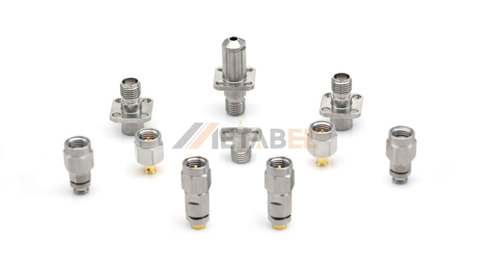
Need help bridging 18 GHz or 26.5 GHz SMA assemblies to 2.92mm or 1.85mm test ports? Contact Metabee to get custom RF cable assemblies and precision between-series adapters built to your specifications.
How to Choose the Right SMA Frequency Rating: 4-Step Buyer's Checklist
Before finalizing your part number, run through this four-step engineering checklist to balance RF performance and cost:
- Apply a 20% Frequency Headroom Rule: If your signal or third harmonic reaches 15 GHz, avoid running a 12.4 GHz connector at its limit. Step up to a DC–18 GHz or DC–26.5 GHz model for a flatter VSWR curve.
- Match Metallurgy and Dielectric to the Environment: For VNA ports, radar, or wide-temperature (-55°C to +165°C) aerospace modules up to 26.5 GHz, specify passivated stainless steel. Pair it with dual PEI & PTFE insulation for maximum stability. For indoor sub-6 GHz or 18 GHz commercial boards, gold-plated brass with virgin PTFE provides excellent value.
- Align Pin and Flange Geometry with Your Substrate: Verify your flange hole spacing (8.6mm, 12.2mm, or 12.7mm) before ordering. Choose 0.8mm Flat Pin or Ø0.23mm–Ø0.51mm glass-bead sockets to minimize microstrip launch reactance.
- Enforce Calibrated Torque During Assembly: Always use a calibrated 5/16-inch torque wrench during installation. Apply 8 in-lbs for stainless steel SMA connectors and 3–5 in-lbs for brass models.
Related Products
Conclusion: Matching the Right SMA Bandwidth to Your RF System
The SMA connector frequency range is not a single fixed number. Instead, it spans three practical engineering tiers based on internal geometry, metallurgy, and termination design:
- DC to 6 GHz for commercial flexible braided cables (RG174, RG316, LMR series) and reverse-polarity RP-SMA Wi-Fi antennas.
- DC to 18 GHz for standard MIL-STD-348 gold-plated brass and stainless steel connectors insulated with virgin PTFE.
- DC to 26.5 GHz for precision passivated stainless steel connectors engineered with composite PEI & PTFE or PEEK & PTFE dielectrics.
Selecting the right tier protects your signal integrity while keeping hardware costs under control. Below 18 GHz, standard brass connectors deliver reliable 50-Ohm performance. Between 18 GHz and 26.5 GHz, upgrading to precision stainless steel, custom-slotted edge launches, or field-replaceable glass-bead receptacles prevents mode conversion and thermal VSWR drift. For frequencies beyond 26.5 GHz, transitioning to mechanically mateable 3.5mm (34 GHz) or 2.92mm (40 GHz) air-dielectric interfaces ensures mode-free propagation.
At Metabee, we manufacture over 330 standard and high-frequency SMA connector configurations spanning DC–6 GHz, DC–18 GHz, and DC–26.5 GHz. Whether you need bulk OEM pricing, custom flange geometries, or rapid engineering support, contact us today and our RF specialists will respond within 24 hours.
Frequently Asked Questions (FAQ)
Q: What is the maximum frequency of a standard SMA connector?
A: A standard MIL-STD-348 SMA connector has a maximum operating frequency of 18 GHz. Precision extended-range SMA connectors with passivated stainless steel bodies and PEI & PTFE dielectrics operate from DC to 26.5 GHz.
Q: Why are some SMA connectors only rated to 6 GHz?
A: SMA connectors for flexible braided cables (like RG174, RG316, or RG58) and reverse-polarity (RP-SMA) antennas are typically rated from DC to 6 GHz. Above 6 GHz, flexible braid leakage and crimp ferrule impedance transitions increase return loss and attenuation.
Q: Can I use an 18 GHz SMA connector at 24 GHz or 26.5 GHz?
A: An 18 GHz SMA connector will physically pass a 24 GHz signal. However, its looser tolerances and uncompensated PTFE step often cause severe VSWR spikes (>1.5:1) above 18 GHz. For any application between 18 GHz and 26.5 GHz, always specify a dedicated DC–26.5 GHz precision SMA connector.
Q: What coaxial connector should I use if my frequency exceeds 26.5 GHz?
A: If your operating frequency falls between 26.5 GHz and 34 GHz, upgrade to a 3.5mm connector. For 34 GHz to 40 GHz, select a 2.92mm (K-type) connector; both share the 1/4-36 thread and mate directly with SMA interfaces. For 50 GHz to 67 GHz, use 2.4mm or 1.85mm millimeter-wave connectors.
