
Advancements in technologies such as intelligent driving, surround-view cameras, multi-display cockpits, and automotive Ethernet are driving in-vehicle data transmission rates into the multi-gigabit range. Engineers require solutions that offer robust, high-speed connectivity while accommodating the space constraints of vehicle interiors.
With their superior high-frequency performance, modular housing design, and reliable shielding capabilities, H-MTD automotive connectors have become a popular choice for high-speed in-vehicle communication.
This guide provides a detailed overview of H-MTD connectors—covering their categories, selection criteria, and practical application scenarios—to assist you in selecting the right solution.
What Is an H-MTD Connector?
What Is H-MTD?
H-MTD, which stands for High-Speed Modular Twisted-Pair Data, is a high-speed modular twisted-pair data connector system for vehicles developed by Rosenberger. Designed for the transmission of high-speed differential signals between in-vehicle electronic devices, the system supports Automotive Ethernet, LVDS, and various digital communication protocols.
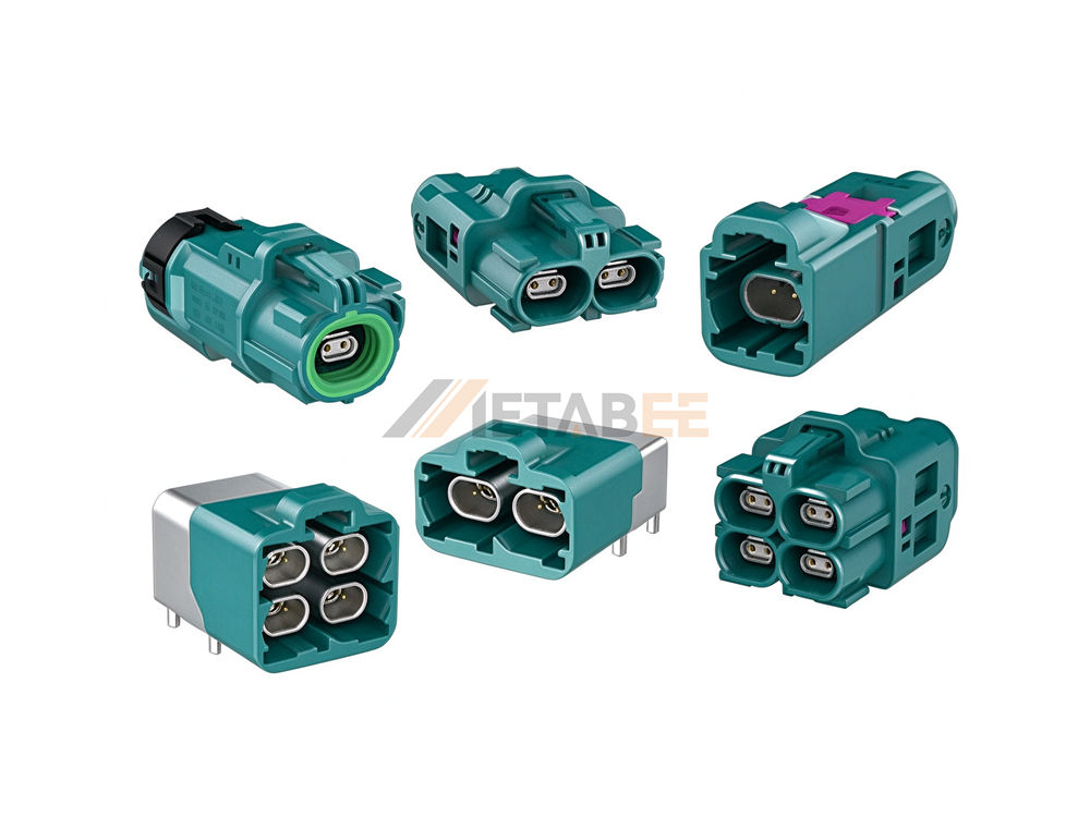
Unlike general-purpose connectors, H-MTD is optimized for differential twisted-pair signal transmission and supports both shielded twisted-pair (STP) and unshielded twisted-pair (UTP) cabling solutions.
Its modular design enables the deployment of single or multiple high-speed data channels within constrained automotive installation environments, meeting the practical requirements of vehicle wiring architectures.
Key Features of the H-MTD Connector
- Modular Port Design
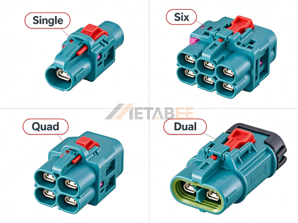
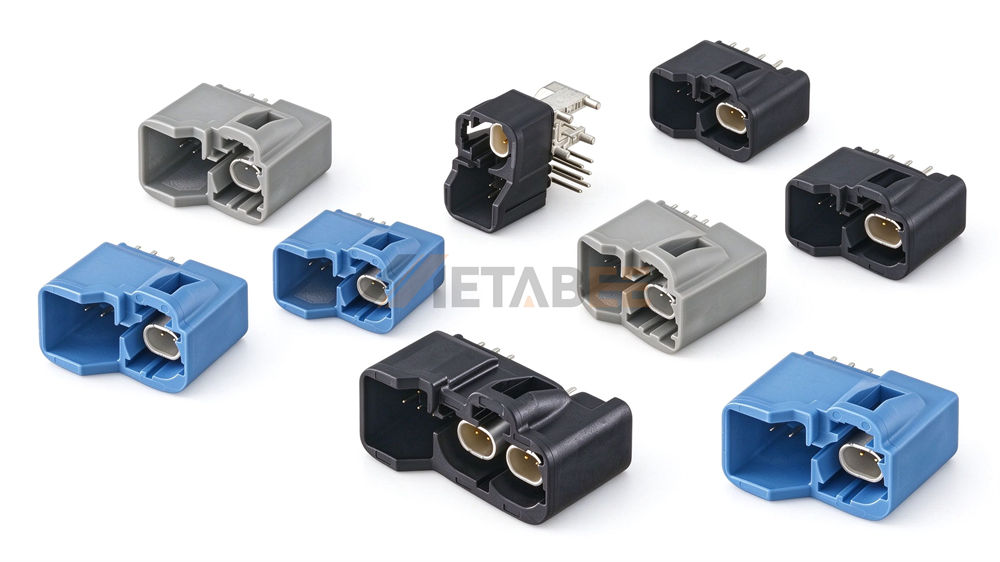
Available in various configurations, including single, dual, quad, and hex-port versions, as well as options with integrated power pins. Integrating multiple ports into a single housing saves installation space within the vehicle and allows for flexible adaptation to diverse equipment and wiring harness layouts.
- Twisted-Pair Differential Transmission
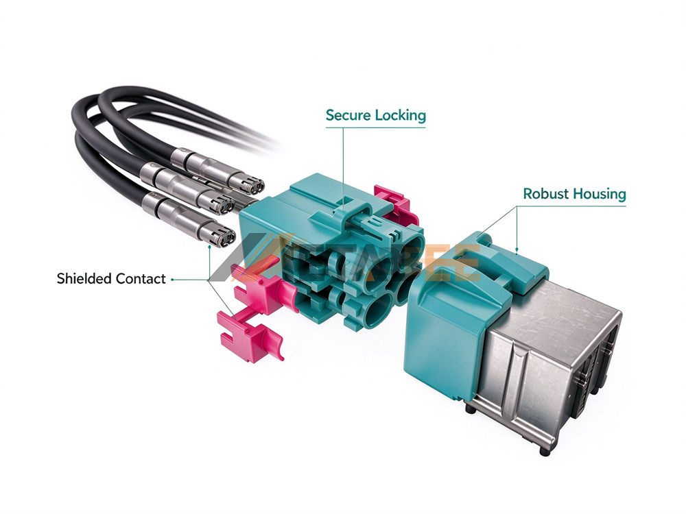
Compatible with both STP (Shielded Twisted Pair) and UTP (Unshielded Twisted Pair) cables. Differential signal pairs form a robust high-speed transmission channel, making the system suitable for applications such as cameras, displays, and control units.
- High-Speed Transmission Performance
Supports frequencies up to 20 GHz and data transmission rates up to 56 Gbps, meeting the high-bandwidth communication requirements of automotive systems.
Note: The 56 Gbps maximum rate for H-MTD refers to the hardware capability of the connector itself; actual bandwidth depends on factors such as cabling, communication protocols, and SerDes chips. The connector alone cannot guarantee that the system will achieve a 56 Gbps rate.
- Flexible Configuration
Various port and cable combinations support application scenarios involving multiple automotive sensors and the transmission of massive amounts of image data.
H-MTD Coding
Why Do H-MTD Connectors Need Coding?
Automotive wiring harnesses contain many connectors that may look similar. If connectors used for different signal links could be freely interchanged, they could be mismatched during assembly, affecting harness installation and system operation.
H-MTD uses coding to distinguish how different connectors are designed to mate. Each code corresponds to a different physical structure, so only compatible plugs and jacks can connect properly. Housing colors provide a visual aid, helping assembly personnel identify products quickly.
The main purpose of coding is to prevent connector mismating. It does not indicate data rate or communication protocol, nor does it mean that products with different codes have different electrical performance.
How Do H-MTD Coding Variants Differ?
The main differences between H-MTD coding variants are their physical structures and housing colors. Their electrical performance and impedance remain the same.
- Different physical structures: The mating profiles differ between coding variants, including the shape or position of keying protrusions, guide slots, and locating features. Only the corresponding plug and jack can mate correctly, helping reduce the risk of mismating.
- Different housing colors: Different codes usually use different colors, making them easier to identify visually during production, installation, and maintenance. Color is an identification aid and cannot replace the product code or interface specifications.
- Consistent electrical performance and impedance: Coding is used to identify mechanical mating configurations, not to distinguish electrical parameters. When selecting a connector, the cable type, transmission requirements, and interface configuration should still be confirmed based on the system design.
H-MTD Coding Reference
H-MTD offers several coding options. The table below lists common codes and their corresponding housing colors. Actual availability may vary by product series.
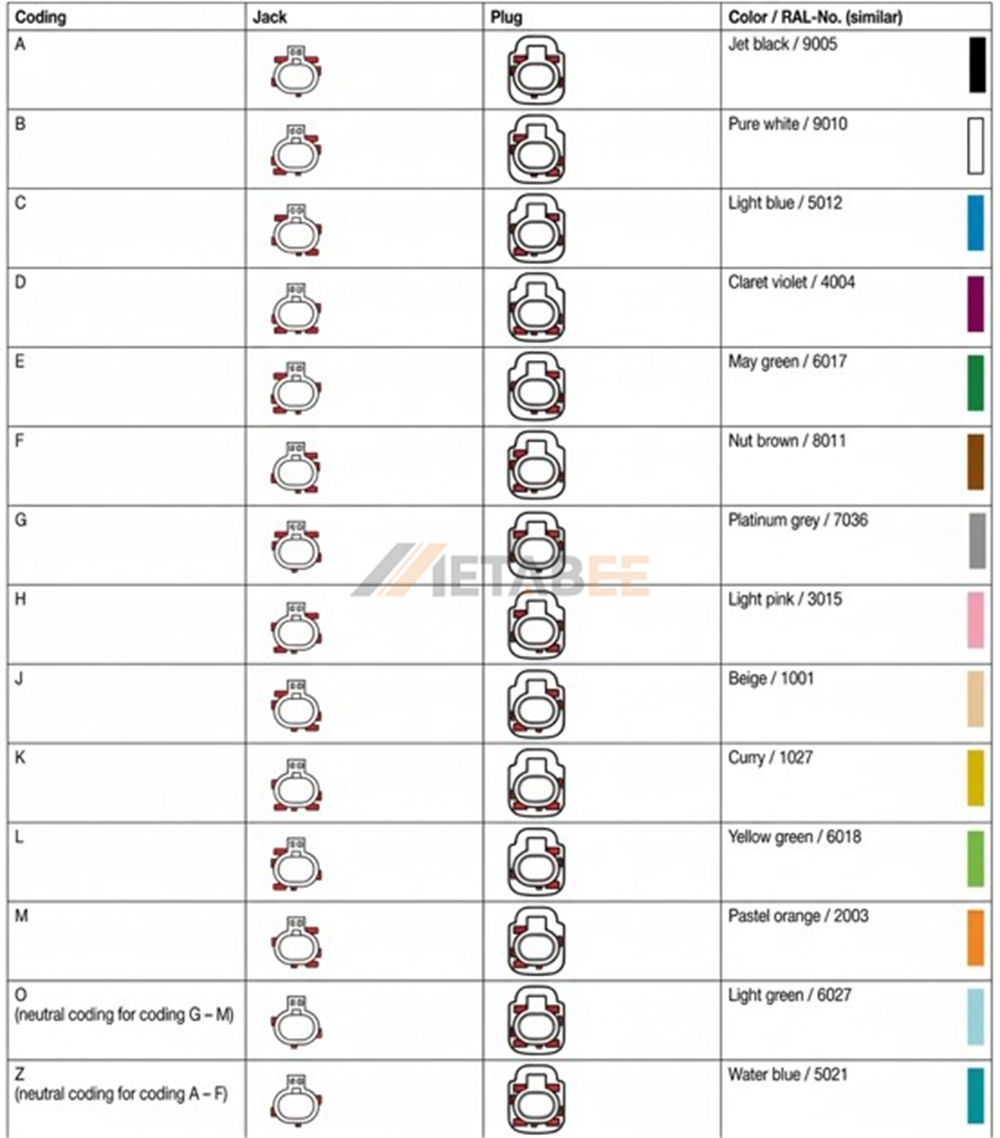
Please note that Z coding is a neutral coding option, and its mating rules differ from those of other codes. When selecting or replacing a connector, refer to the coding information for the device interface, mating connector, and product drawings. Housing color alone is not enough to determine compatibility.
H-MTD Connector Types
Standard H-MTD Connectors
Standard H-MTD connectors are used to connect cables to devices, and PCB-mount versions are also available. They can be classified by the following features.
Classified by Gender
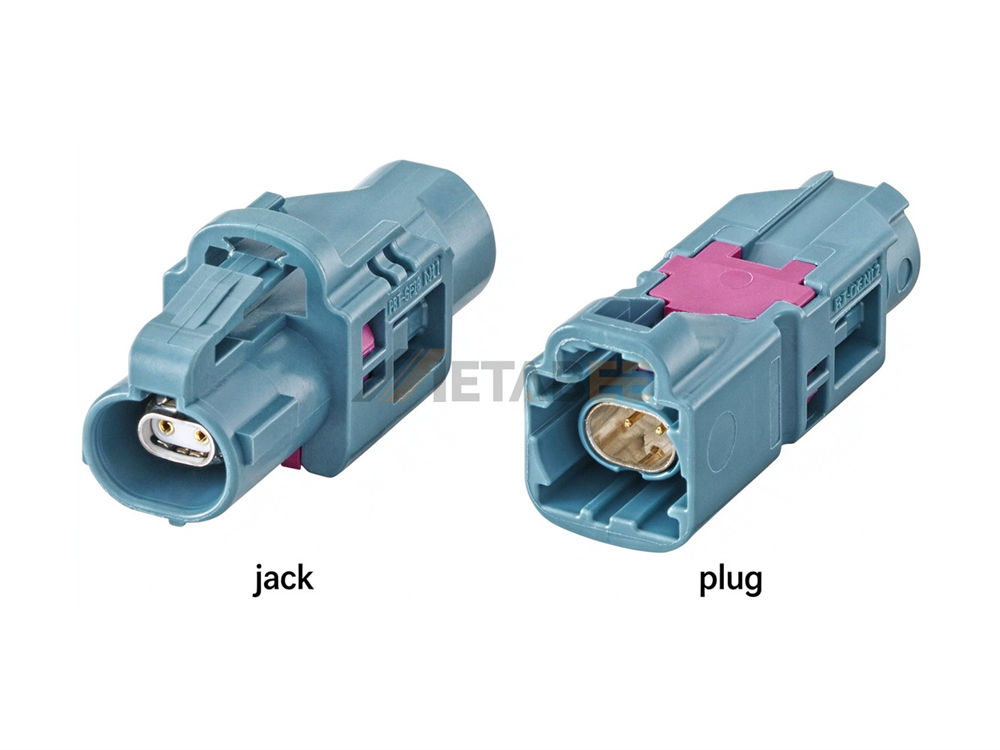
H-MTD connectors are available as plugs and jacks. They must be matched according to the interface design of the device and cable ends.
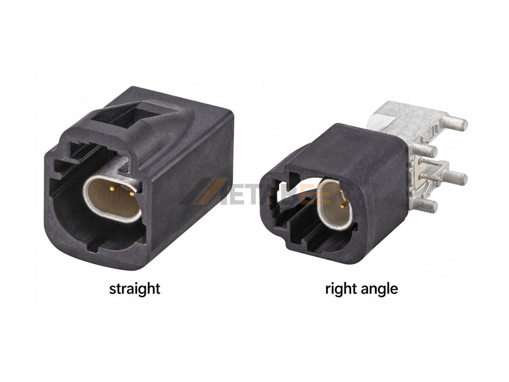
Classified by Orientation
Common configurations include straight and right-angle connectors, depending on the direction of the interface or cable exit. Straight connectors follow the mating direction, while right-angle connectors change the connection or cable-exit direction to suit different installation spaces and harness routes.
Classified by Number of Ports
H-MTD housings are available in single-, dual-, quad-, and six-port configurations, accommodating different numbers of data connections. Multi-port designs allow several data links to be arranged within one interface area. The number of ports should match the device interface and wiring harness design.
Classified by Mounting Type
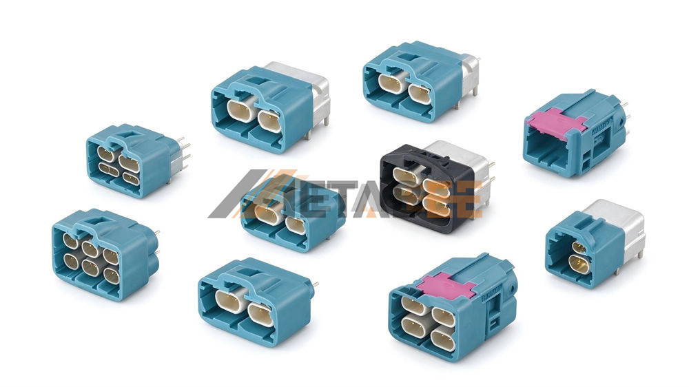
- Cable side: The wires are connected by crimping. Pre-assembled H-MTD cable assemblies are also available.
- PCB side: Connectors can be mounted on the board using SMT (surface-mount technology) or DIP (through-hole mounting).
Waterproof H-MTD Connectors
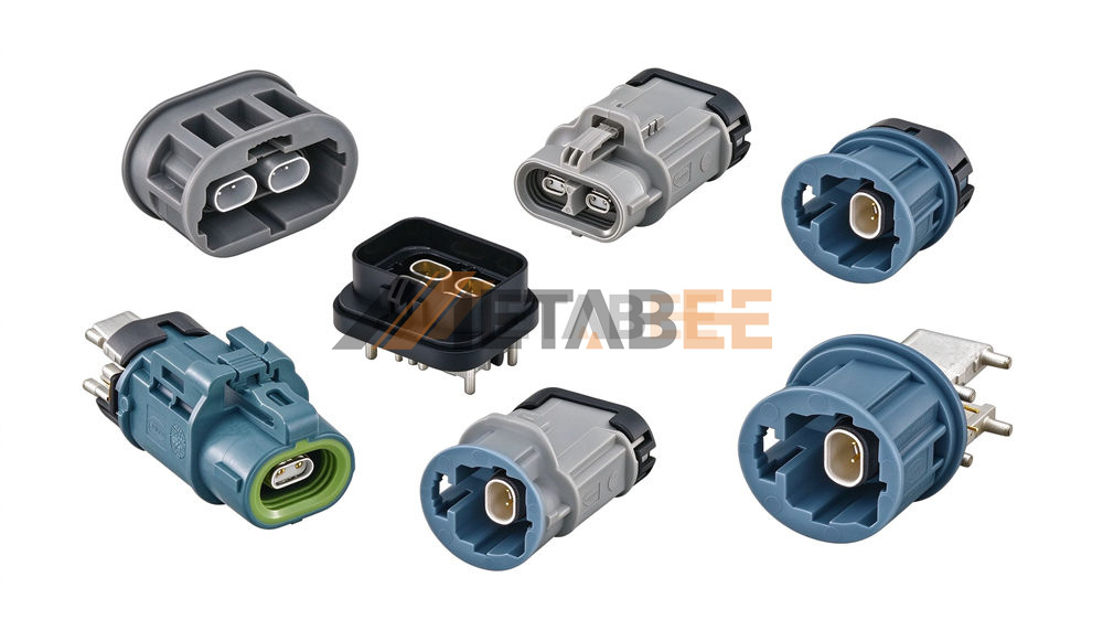
Waterproof H‑MTD connectors add integrated sealing structures to shield connection points for wet‑location installation requirements.
Available in various forms—such as cable-end and PCB-mount types—and in single-port, dual-port, and multi-port configurations, these connectors retain the high-speed data interface of the H-MTD series while offering waterproof and dustproof solutions tailored to diverse installation environments.
H-MTD+ 6 Power Pin
The H-MTD+ 6 Power Pin adds six power contacts to the standard H-MTD data connection. Since data transmission and power delivery utilize separate contacts, a single connector assembly can handle both data links and power supply, thereby reducing the need for separate data and power interfaces on the device.
H-MTD+ 6 Power Pin connectors currently available on the market feature various signal port configurations:
- Connectors with 2 signal contacts and 6 power contacts
- Connectors with 4 signal contacts and 6 power contacts
The rated current per power pin is ≤1.5A DC (connector body only). Real‑world current capacity depends on harness specs, PCB layout and ambient temperature.
Additionally, H-MTD+ connectors are available in various configurations, including cable-mount and PCB-mount versions, as well as straight, right-angle, and waterproof designs.
H-MTD e
H-MTD e is part of the H-MTD product family and is designed for unshielded twisted-pair (UTP) links, including automotive Ethernet applications. Unlike standard H-MTD, it is specifically designed for UTP cables. Product availability is limited, and specific models may vary by supplier.
Quick Comparison of Four H-MTD Configurations:
|
Type |
Key feature |
Intended requirement |
|
Standard H-MTD |
Multiple port counts and connection formats |
Port count, interface type, and cable compatibility |
|
Waterproof H-MTD |
Sealing structure for protection |
Protection requirements at the installation location |
|
H-MTD+ 6 Power Pin |
Integrates signal and power contacts |
A connection that carries both data and power |
|
H-MTD e |
Ethernet connection for UTP |
UTP-based automotive Ethernet |
H-MTD Applications
Automotive Ethernet
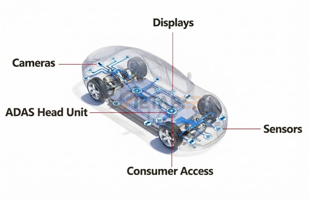
Automotive Ethernet connects electronic control units (ECUs) within a vehicle and can also carry data from sensors, cameras, and other systems. As in-vehicle networks handle increasing amounts of data, connectors must support the required data links within limited installation space.
H-MTD’s modular design accommodates different port counts and wiring layouts, making it suitable for automotive Ethernet connections. The specific product should be selected based on the link’s transmission requirements, cable type, and interface configuration.
ADAS and Camera Systems
ADAS cameras capture image data and transmit it to a control unit or processing device. In systems that use differential twisted-pair links, H-MTD can provide the connection between the camera and the processing device.
Where multiple cameras need to be connected in a limited space, multi-port configurations can help consolidate several data connections. If a system uses coaxial cable, it requires a connector solution designed for coaxial links; H-MTD cannot be used as a direct substitute.
Infotainment and Display Systems
Video and other high-speed data need to travel between the head unit, instrument cluster, center display, and rear-seat displays. H-MTD can be used for high-speed data connections between these devices, while its multi-port design can support layouts that connect several displays in one area.
The connector establishes the physical link, while the system design determines the data being transmitted and the communication protocol used. The connection solution for a display system should therefore match the device interface and link requirements.
How to Choose H-MTD Connector
Selecting an H-MTD connector involves considering the data link, connector configuration, and installation environment. The previous sections covered coding and the main product types. This section focuses on the specifications and operating conditions to check during selection.
Confirm the Data Link and Cable Requirements
First, identify the communication protocol and target data rate of the link. H-MTD has a nominal impedance of 100 Ω and supports frequencies up to 20 GHz. However, the connector’s maximum hardware capability of 56 Gbps does not mean the entire link will necessarily achieve that data rate. Actual performance also depends on the cable, protocol, devices, and signal integrity design.
The cable type must also be compatible with the connector. Confirm whether the application uses shielded twisted-pair (STP) or unshielded twisted-pair (UTP) cable, and check that the conductor size and cable outer diameter meet the connector requirements. For pre-assembled cable assemblies, make sure the cable length and connectors at both ends suit the wiring layout.
Match the Connector Interface and Configuration
The coding, connector gender, and number of ports must match the device interface. The connector orientation and mounting type should be selected based on the available space and harness routing, such as choosing a straight or right-angle design and a cable-side or PCB-side connector.
PCB-side connectors must meet the board layout and mounting requirements, while cable-side connectors must match the cable specifications and termination method. Refer to the product drawings and specifications for the selected model to confirm the exact configuration.
Check the Installation Environment and Project Standards
The connector’s installation location affects its protection and qualification requirements. Check the following:
- Environmental conditions: The temperature range, vibration and shock levels, and potential exposure to moisture or dust.
- Sealing requirements: If protection against water or dust is required, select an appropriate waterproof version and check the protection rating and test results for the specific model.
- Project standards: The project may require compliance with standards such as LV214 or USCAR. Qualification results can vary by model, so confirm that the selected product meets the project requirements.
Confirm Power and Assembly Requirements
If data and power need to be transmitted through the same connection point, consider the H-MTD+ 6 Power Pin. Its power contacts have a rated current of up to 1.5 A DC. Actual current capacity also depends on the cable, PCB design, and ambient temperature, so refer to the specifications for the specific model.
Before installation, also check that the connector’s cable-exit direction, harness bending space, and fixing points suit the equipment layout. If on-site crimping or repairs are required, confirm the availability of the appropriate contacts, tools, and assembly procedures. For pre-assembled cable assemblies, verify the assembly length and connector configuration.
Conclusion
H-MTD is a modular connector system for high-speed differential data transmission in vehicles. Its coding helps prevent mismating, while its range of configurations supports applications such as automotive Ethernet, ADAS cameras, and infotainment and display systems.
When choosing an H-MTD connector, confirm the data link and cable requirements, then match the connector to the device interface, installation environment, and any power needs.
If you are looking for H-MTD connectors and pre-assembled cable assemblies, or need to place a bulk order, Metabee can help you review product configurations and project requirements. For further assistance, please contact us.
Related Products
FAQs
Q1: What is the H-MTD Z connector?
In H-MTD product descriptions, "Z" typically refers to "Z-coding"; some product names omit the word "Code" and are simply labeled "H-MTD Z." However, "Z" can also be part of a model number or configuration identifier, so it should be interpreted in the context of the full product name.
Q2: What transmission rates can H-MTD automotive Ethernet achieve?
H-MTD automotive Ethernet supports rates of 100 Mbps, 1 Gbps, 2.5 Gbps, 5 Gbps, and 10 Gbps, with a maximum capability of 10 Gbps.
Q3: What advantages does H-MTD offer over HSD connectors?
Compared to HSD connectors, the H-MTD series supports higher data transmission rates and offers a wider range of port configurations, making it suitable for applications requiring the integration of multiple high-speed data connections.
Q4: Which cable types does H-MTD support?
H-MTD product solutions are compatible with cables such as Shielded Twisted Pair (STP) and Unshielded Twisted Pair (UTP), and there are also products designed for specific cable types.
Q5: Does H-MTD support 4K high-resolution displays?
Yes. H-MTD can be used for data connections in display systems with 4K or higher resolutions; actual support capabilities depend on the transmission protocol and data rate used by the display link.
