
In the rapidly evolving landscape of industrial automation, smart factories, and Industry 4.0, space is often at a premium. Engineers and system integrators are constantly seeking ways to pack more functionality into smaller form factors without sacrificing reliability or performance. Enter the M8 connector.
But exactly what is an M8 connector, and why has it become such a ubiquitous standard in modern control systems?
This comprehensive guide will provide a deep dive into the M8 connector, covering its pinouts, coding variations, technical specifications, and key differences from M12 connectors. Whether you are an electrical engineer designing a new robotics system or a procurement manager sourcing components, this guide will help you select the right M8 connector for your specific application.
What is an M8 Connector?
An M8 connector is a type of circular electrical connector distinguished by its 8-millimeter metric locking thread. Standardized under IEC 61076-2-104, it is specifically designed to provide robust, waterproof, and vibration-resistant connections for sensors, actuators, and switches in industrial automation networks.
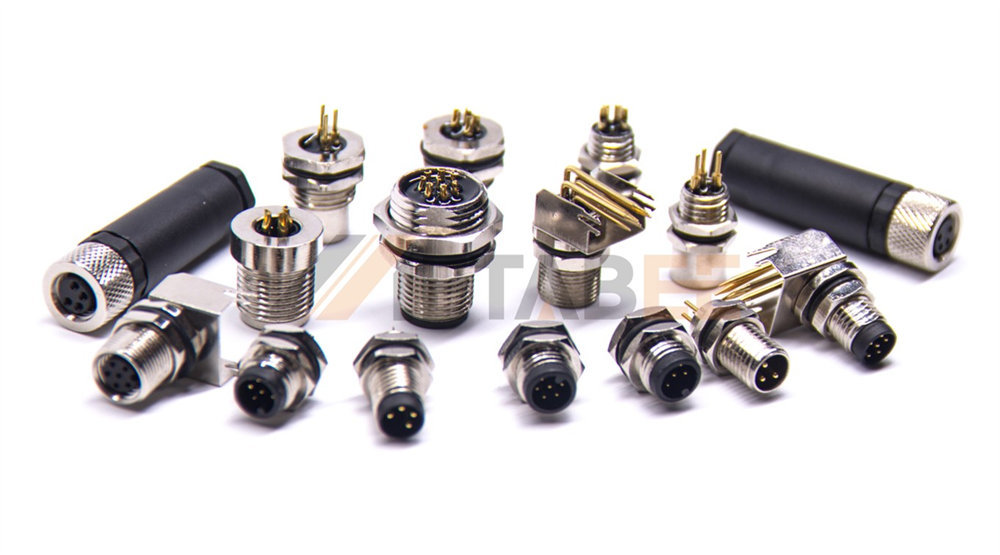
Historically, as machinery became more compact and sophisticated, standard connectors proved too bulky for miniature sensors and tight installation spaces. The M8 connector was developed as a space-saving solution. Despite its small footprint, it offers exceptional durability, capable of withstanding harsh industrial environments involving dust, moisture, chemicals, and continuous mechanical stress.
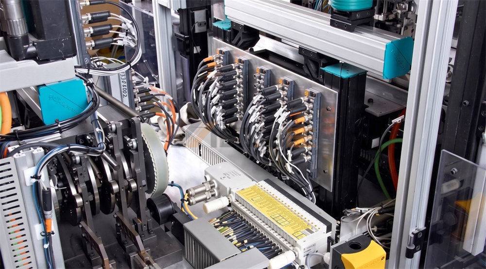
Today, if you look inside a modern automated assembly line, packaging machine, or robotic workcell, you will undoubtedly find M8 connectors. These essential components facilitate the critical flow of data, signals, and power between field-level devices and central control systems.
M8 Connector Pinout, Coding, and Color Code
To ensure seamless integration and prevent disastrous wiring errors on the factory floor, M8 connectors rely on standardized pinouts, mechanical coding, and wire color codes.
Pin Configurations Overview
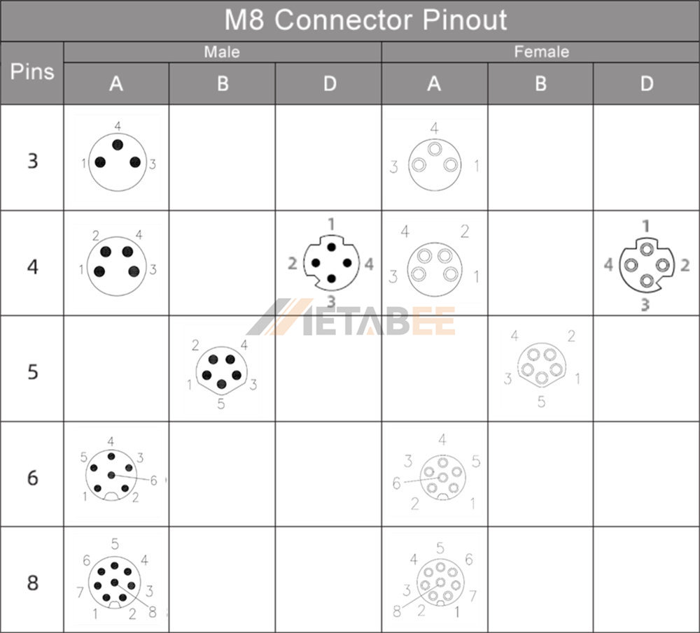
The "pinout" refers to the number of contact pins within the connector and how they are arranged. M8 connectors are available in various pin counts (ranging from 3 to 8 pins), with each pin assigned a specific function, such as supplying DC power, transmitting analog signals, or transferring digital data. Choosing the correct pinout is the first step in ensuring your sensor or actuator can communicate with your I/O module.
The Coding System
In industrial environments, multiple connectors are often clustered tightly together on a distribution box. To prevent an engineer from accidentally plugging a power cable into a data port (which could short-circuit and destroy expensive equipment), M8 connectors utilize a "coding" system.
Coding involves internal keyways and physical mating profiles molded into the connector housing. These act as a lock-and-key mechanism to prevent mismating. For M8 connectors, there are three primary coding types you will encounter:
l A-Coding: The most universal standard. It is primarily used for sensors, actuators, DC power distribution, and basic analog or digital signal transmission.
l B-Coding: Featuring a reversed keyway to prevent mating with A-coded components, B-coded M8s are specifically utilized for specialized network signals, most notably Fieldbus connections like PROFIBUS.
l D-Coding: Designed for high-speed data transmission. D-coded M8 connectors are the standard for Industrial Ethernet protocols, such as PROFINET and EtherCAT, capable of supporting network speeds up to 100 Mbps.
This mechanical mismating prevention is crucial for system safety and ensures quick, error-free deployment on the factory floor.
Standard M8 Color Code Chart
For field-wireable M8 plugs and pre-molded flying-lead cables, the industry adheres to a standard color code for the internal wires. Below is the most common color-coding standard used for standard 3-pin and 4-pin A-coded sensor connectors:
|
Pin Number |
Wire Color |
Typical Function (Sensors) |
|
Pin 1 |
Brown (BN) |
Positive Power (+24V DC) |
|
Pin 2 |
White (WH) |
Data / Secondary Signal (NC - Normally Closed) |
|
Pin 3 |
Blue (BU) |
Ground / Negative Power (0V) |
|
Pin 4 |
Black (BK) |
Primary Output Signal (NO - Normally Open) |
M8 Connector Color Code Overview:

Note: Always verify the wiring diagram provided by your specific sensor manufacturer, as custom applications may deviate from standard color assignments.
Related Post: The Ultimate Technical Guide to M8 Connector Pinout: 3-Pin to 8-Pin Configurations
Structure and Materials
The reliability of an M8 connector is heavily dependent on the materials used in its construction. A high-quality M8 connector is built to survive mechanical wear, chemical exposure, and electrical degradation.

Contacts (Pins and Sockets)
To ensure low contact resistance and high electrical conductivity, the internal contacts are typically manufactured from brass or phosphor bronze. For industrial grades, these contacts are heavily gold-plated over a nickel underplate. The gold plating prevents oxidation and ensures reliable signal transmission even after hundreds of mating cycles.
Housing and Overmolded Cables
The outer jacket and the connector body are made from specialized polymers.
l TPU (Thermoplastic Polyurethane): Often used for the connector body itself, providing a rugged, impact-resistant shell.
l PUR (Polyurethane): Highly recommended for harsh environments. It offers excellent resistance to oil, chemicals, and abrasion, and remains highly flexible, making it ideal for robotic drag chains (C-tracks).
l PVC (Polyvinyl Chloride): A cost-effective solution for static installations or environments with moderate mechanical stress. It is suitable for general-purpose applications but is less resistant to aggressive cutting oils than PUR.
Coupling Mechanisms
The defining feature of the M8 is its locking nut. These are usually made from nickel-plated brass or stainless steel (for food and beverage or highly corrosive environments). They feature knurled or hexagonal designs, allowing them to be tightened with a torque wrench to ensure a vibration-proof seal that will not rattle loose during machinery operation.
Technical Specifications
When reviewing an M8 connector datasheet, engineers must pay close attention to several critical specifications to ensure it meets the demands of their circuit:
Electrical Ratings
l Rated Voltage: Usually 60V AC/DC for 3-pin variants, and 30V AC/DC for 4, 5, 6, and 8-pin variants.
l Rated Current: Generally supports 3A for 3, 4, and 5-pin configurations. As pin density increases (for 6 and 8 pins), the current capacity typically drops to 1.5A per pin to manage heat dissipation.
Environmental Ratings (IP Rating):
M8 connectors are renowned for their Ingress Protection. When properly mated and locked, standard M8 connectors achieve an IP67 rating (dust-tight and protected against temporary immersion in water). Many premium models reach IP68 (continuous submersion) or IP69K (protection against high-pressure, high-temperature washdowns, essential for the food and pharmaceutical industries).
Operating Temperature
Typically rated to perform flawlessly in extreme temperatures ranging from -25°C to +85°C, with some specialized variants capable of handling up to +125°C.
Mechanical Lifespan
Designed for durability, they usually guarantee a minimum of >500 mating cycles without degradation of the IP rating or contact resistance.
Standard M8 Connector Specifications Table
To provide a comprehensive overview, here is a detailed summary table of the standard technical parameters you can expect from industrial-grade M8 connectors:
|
Parameter |
Standard Specification / Range |
|
Standard Compliance |
IEC 61076-2-104 |
|
Number of Contacts |
3, 4, 5, 6, 8 pins |
|
Coding Types |
A-Coding, B-Coding, D-Coding |
|
Rated Voltage |
60V (3-pin) / 30V (4, 5, 6, 8-pin) |
|
Rated Current |
1.5A to 4.0A (varies by pin density) |
|
Contact Resistance |
≤ 5 mΩ (milliohms) |
|
Insulation Resistance |
≥ 100 MΩ (megaohms) |
|
Degree of Protection |
IP67 / IP68 (in locked condition) |
|
Operating Temperature |
-25°C to +85°C (standard) |
|
Overvoltage Category |
II |
|
Shell/Nut Material |
Nickel-plated brass, Stainless steel, or Plastic |
|
Contact Material |
Brass / Phosphor bronze (Gold-plated) |
|
Mechanical Operation |
> 100 mating cycles |
Types of M8 Connectors
The true versatility of the M8 connector lies in its various configurations tailored for specific environments, signal requirements, and physical installation constraints.
By Coding and Number of Pins
The most critical classification for an engineer is the combination of pin count and mechanical coding. This determines both the electrical capacity and the specific communication protocol the connector can handle.
l M8 D-Coded 4-Pin Connectors
The table below lists the parameters and applications of these 6 connectors.
|
Configuration |
Rated Voltage |
Rated Current |
Primary Applications & Use Cases |
|
3-Pin A-Coded (3A) |
60V |
3A - 4A |
Standard proximity switches, basic photoelectric sensors, limit switches. Provides Power (+), Ground (-), and one signal. |
|
4-Pin A-Coded (4A) |
30V - 60V |
3A - 4A |
Dual-output sensors (Normally Open & Normally Closed simultaneous outputs), simple actuators, LED machine lighting. |
|
4-Pin D-Coded (4D) |
30V |
4A |
Industrial Ethernet and fast data transmission. Supports protocols like PROFINET and EtherCAT (up to 100 Mbps). |
|
5-Pin B-Coded (5B) |
30V |
3A |
Specialized Fieldbus networks. Primarily used for PROFIBUS or DeviceNet communication lines to prevent mismatching. |
|
6-Pin A-Coded (6A) |
30V |
1.5A |
Measurement instruments and complex sensors requiring multiple signal channels or separate power supplies in a tight space. |
|
8-Pin A-Coded (8A) |
30V |
1.5A |
The highest pin density for M8. Used for advanced multi-signal devices, absolute rotary encoders, vision cameras, and compact I/O boxes. |
By Assembly Style: Plugs vs. Receptacles
Depending on where the connector is situated within the control network, M8 connectors are generally classified into Plugs (for cable ends) and Receptacles (for panel or device mounting).

Plugs (Cable-Mounted Connectors)
These are typically the "male" or "female" connectors attached to a cable that plug into a device or distribution box.
l Field-Wireable Plugs: These allow technicians to manually terminate the wires on-site using screw terminals, solder cups, or insulation displacement connection (IDC) technology. They are ideal for custom-length cable routing or field repairs where replacing an entire cable run is impractical.
l Overmolded Cable Assemblies: Also known as molded cordsets, these come pre-attached to a specific length of cable (often PUR or PVC) directly from the factory. The connector housing is molded over the wire terminations, offering vastly superior strain relief and guaranteed waterproof IP67/IP68 sealing out of the box.
Receptacles (Panel or Board-Mounted)
M8 receptacles are the fixed connectors installed directly onto the machine housing, control cabinet, or sensor body to accept incoming plugs.
By Termination Method:
l Solder Cup Receptacles: The pins have small cups on the back where individual wires are manually soldered. Useful for prototype devices, small production runs, or manual wiring harnesses.
l PCB Mount Receptacles: The connector features straight or angled pins designed to be soldered directly onto a Printed Circuit Board (PCB) inside the device via through-hole (DIP) technology.
By Mounting Position:
l Front-Mount: The receptacle is inserted from the outside (front) of the panel and secured with a locking nut on the inside. This leaves the fastening mechanism hidden inside the device.
l Rear-Mount: The receptacle is pushed through the panel from the inside and secured with a nut on the outside. This is often preferred when the internal components (like a pre-assembled PCB) are pushed up against the housing wall.
By Orientation
Space constraints on the factory floor often dictate the physical shape of the connector housing:
l Straight: The traditional design where the plug or receptacle body forms a straight line with the cable or mating axis. Best for open spaces without depth restrictions.
l Right-Angle (90-Degree): The cable or connector housing exits perpendicular to the mating axis. This is highly valuable in extremely tight spaces, preventing severe cable bends that could break internal wires and keeping the profile flush against the machine wall.

M8 vs. M12 Connectors: Understanding the Difference
The most common question engineers ask is: Should I use an M8 or an M12 connector? While both belong to the same family of circular industrial connectors, they serve different primary purposes.
l Size and Footprint: The most obvious difference is the locking thread size (8mm vs. 12mm). The M8 is roughly 30% smaller. If you are wiring a massive robotic arm, M12 is standard. If you are wiring miniature pneumatic grippers on the end of that robotic arm, M8 is required.
l Power and Data Capabilities: Because the M12 has a larger housing, it can accommodate thicker pins and larger wire gauges. Thus, M12 connectors can handle much higher currents (up to 16A in some power encodings) and complex data (up to 10 Gigabit Ethernet with X-coding). The M8 is restricted to lower power (typically max 4A) and Ethernet speeds (up to 100Mbps).
l Pin Density: M12 connectors can easily house up to 12 or 17 pins, whereas the M8 maxes out at 8 pins.
M8 vs. M12 Quick Comparison Table
|
Feature |
M8 Connector |
M12 Connector |
|
Locking Thread Size |
8 mm |
12 mm |
|
Footprint / Size |
Miniature, ultra-compact |
Standard, robust |
|
Max Pin Count |
Up to 8 Pins |
Up to 17 Pins |
|
Max Current Capacity |
Typically 4A (lower for high pin counts) |
Up to 16A (in specific power codings) |
|
Max Data Speed |
Up to 100 Mbps (D-Coding) |
Up to 10 Gbps (X-Coding) |
|
Primary Applications |
Micro-sensors, limit switches, lightweight robotics, tight spaces |
Heavy-duty sensors, main I/O distribution, power transmission, high-speed data |
In summary, choose M12 for heavy-duty power, complex gigabit networking, and rugged environments. Choose M8 for micro-sensors, space-constrained automation, and lightweight robotic applications.
Primary Applications of M8 Connectors
Due to their robust yet miniature design, M8 connectors are heavily integrated into the following areas:
l Sensors and Actuators: The backbone of factory automation. Almost all modern miniature photoelectric, inductive, capacitive, and ultrasonic sensors utilize M8 interfaces.
l Robotics and Conveyor Systems: In automated warehousing and assembly, M8 connectors link micro-switches and pneumatic valves on moving parts where heavy cables would cause drag or mechanical failure.
l I/O Distribution Boxes: Passive junction boxes often feature multiple M8 ports to aggregate signals from various localized sensors before sending them via a single master trunk cable (usually an M12 or M23) to the PLC.
l Measurement and Control Instruments: Used in precision testing equipment, fluid level monitors, and pressure transmitters where reliable signal integrity is non-negotiable.
How to Select the Right M8 Connector for Your Project
Selecting the wrong connector can lead to intermittent signal failures, costly machine downtime, and safety hazards. Follow these steps to ensure you choose the right component:
l Match the Pin and Coding: Always start with the device manual. If your sensor requires a 4-pin A-coded input, your cable must match exactly.
l Evaluate the Environment (IP Rating & Materials): If the connector will be exposed to cutting fluids, oils, or constant flexing in a robotic drag chain, specify a PUR cable. If it requires washdowns, ensure an IP68 or IP69K rating.
l Determine Shielding Requirements: In environments with high Electromagnetic Interference (EMI)—such as near large motors, VFDs, or welding equipment—opt for shielded M8 connectors. Unshielded versions are fine for basic sensors in low-noise environments, but shielded versions are mandatory for data (like Ethernet) or sensitive analog signals.
l Partner with a Reputable Supplier: Quality matters. Choosing a reliable manufacturer like Metabee ensures that you receive connectors with genuine gold-plated contacts, rigorous IP testing, and precise mechanical tolerances that guarantee long-term stability on your production line.
Conclusion & Next Steps
Understanding "What is an M8 connector" is essential for anyone involved in industrial automation design and maintenance. Despite its small size, the M8 connector is a titan of reliability, enabling the miniaturization and data-driven intelligence of Industry 4.0. By carefully considering pin counts, coding, materials, assembly styles, and environmental ratings, you can ensure a robust physical layer for your automated systems.
If you are currently designing a new automated system, facing space constraints, or experiencing failures with your current wire harnesses, expert help is available. Contact the engineering team at Metabee today to discuss your project requirements, request free samples, or explore our custom M8 cable assembly solutions tailored to your exact specifications.
Related Products
Frequently Asked Questions (FAQs)
Q1: Can M8 connectors transmit data, or are they only for power and simple signals?
A: Yes, M8 connectors can reliably transmit data. While A-coded M8s handle simple digital/analog signals, the 4-pin D-coded (4D) M8 connector is specifically designed for Industrial Ethernet protocols like PROFINET, supporting speeds up to 100 Mbps.
Q2: What is the main difference between PUR and PVC M8 cable assemblies?
A: PVC (Polyvinyl Chloride) is an affordable option for static applications with minimal mechanical stress. PUR (Polyurethane) is highly durable, offering superior resistance to cutting oils, chemicals, and abrasion. PUR is highly flexible and is the mandatory choice for continuous-flex applications like robotic drag chains.
Q3: Are M8 connectors waterproof?
A: Yes, when correctly mated and tightened to the specified torque, standard M8 plugs and receptacles are waterproof. Most carry an IP67 rating (protected against temporary submersion). High-end variants designed for extreme environments can achieve IP68 (continuous submersion) or IP69K (high-pressure washdown) ratings.
Q4: How do I wire a field-wireable M8 plug?
A: Field-wireable M8 plugs usually feature screw terminals or solder cups. You must follow the industry-standard color code (e.g., Pin 1: Brown, Pin 3: Blue, Pin 4: Black) and use a precision screwdriver or soldering iron to secure the wires before tightening the backshell to ensure the IP seal.
Q5: Can I get a custom M8 cable assembly if standard lengths don't fit my machine?
A: Absolutely. Specialized B2B manufacturers and custom wire harness providers like Metabee offer bespoke solutions. You can customize cable lengths, jacket materials (PUR/PVC/Teflon), shielding, and even choose to have an M8 plug on one end and a different interface (like an M12 or RJ45) on the other.
