High Voltage Wiring Harness Components - High Voltage Connectors (2)
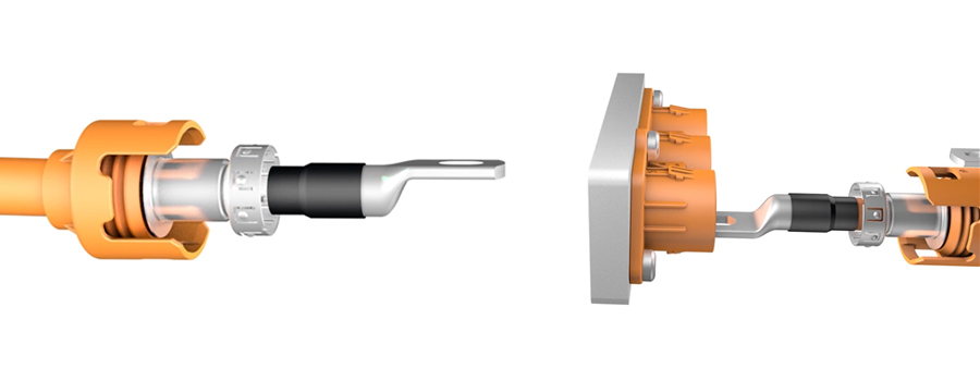
Last paper mainly expounds the basic composition, various classifications, design elements, fault analysis and corresponding measures of high-voltage connectors.
In this paper we will introduce the main points of the design of high-voltage connector contacts, connector insulation structure design, anti-vibration design, anti-rotation structure design, high-voltage resistance performance design.
1. High-voltage Connectors Contact Parts Design Points
The contact connection technology mainly examines the contact area and contact force, including the contact connection between the terminal and the wire, and the contact connection between the terminal and the terminal.
The reliability of the contacts is an important factor determining the reliability of the system, and it is also an important part of the entire high-voltage wire harness assembly. Due to the harsh working environment of some terminals, wires and connectors, the connection between terminals and wires, and the connection between terminals and terminals are prone to various failures. Such as corrosion, aging, and loosening under vibration.
(1) Terminal and wire contact connection
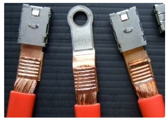
Terminal and wire connection, refers to the middle of the two through the crimping process or ultrasonic welding process to connect. At present, the crimping process and ultrasonic welding process is commonly used in the high-voltage wire harness, each has its advantages and disadvantages.
① Crimp process
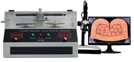
The principle of the crimping process is through the external force of the terminal crimp part of the conductor wire for a simple physical extrusion. The height, width, profile state and pulling force of the terminal crimp is the most core content of the terminal crimp quality, which determines the quality of the crimp.
However, it should be noted that any finely processed solid surface, its microstructure surface is always rough and uneven. Terminals and wires after crimping, not the entire contact surface contact, but scattered on the contact surface of a number of points of contact. The actual contact surface is necessarily smaller than the theoretical contact surface, which is the reason for the higher contact resistance of the crimping process.
Mechanical crimping has a greater impact on the crimping process, such as pressure, crimp height, etc., the need for production control by means of crimp height and profile analysis. So the crimping process is generally consistent crimping, tool wear impact, general reliability.
Mechanical crimping process is mature, the actual application range is very wide, is the traditional process. Almost all large suppliers have taken this process of wire harness products.

② Ultrasonic welding process
Ultrasonic welding is the use of high-frequency vibration wave transmission to the surface of two objects to be welded, under pressure, so that the surface of the two objects rub against each other to form a fusion between the molecular layer.
From the performance point of view, the ultrasonic welding process contact resistance is small, a long time over-current heating is small; safety, fastness, long time vibration state is not easy to loosen off; can be applied to welding between different materials; subject to surface oxidation or plating under the influence; can be monitored through the crimping process related waveform to determine the quality of welding.
Although the equipment cost of the super shot wave welding process is high, and the metal parts welded can not be too thick (generally ≤ 5 mm), but ultrasonic welding as a mechanical process, no current flow throughout the welding process, so there is no heat transfer and resistivity, is the future trend of high-voltage wire harness welding.

(2) Terminal to terminal contact connection
Terminal to terminal contact reliability depends on the contact form of the contact, surface quality, raw material performance and working environment and other factors. In the design of high-voltage contacts such as high-current connectors, the terminal and terminal connection to choose what contact form will directly determine the overall quality and cost of the connector.
One of the basic performance of the connector contact resistance is to have a pin (terminal) and jack (terminal) contact to ensure that there are two main aspects of the requirements:
- Pins and jacks in the insertion of the base resistance must be less than the specified contact resistance;
- Pins and jacks after insertion, to ensure the continuity of the contact between the terminals, can not produce contact instant disconnection or a long time disconnection.
Only to do these two things to ensure that the connector is connected between the high-voltage components of the reliable transmission of high-voltage electricity.
The high-voltage jack contact structure commonly used in the industry at present mainly has three types of leaf spring type, wire spring type and spring coil type. The forms of mutual contact between terminals and terminals are generally classified into three categories: point contact, line contact and surface contact.
① Leaf spring contact
The jack of the leaf spring contact is the crown spring hole, and there is a leaf spring ring placed in the jack, and each leaf spring ring consists of several spring pieces, all of which are arched inward. When the jack is mated with the pin, each spring is in contact with the pin and generates a squeezing force to ensure stable contact at multiple points.
The flat design makes the terminal assembly occupy very little space, which in turn makes the overall size of the connector smaller and reduces the requirement for assembly space.
From the electrical performance point of view, the use of leaf spring contact technology of the terminal contact points less, contact stability is generally, the contact resistance is relatively large.
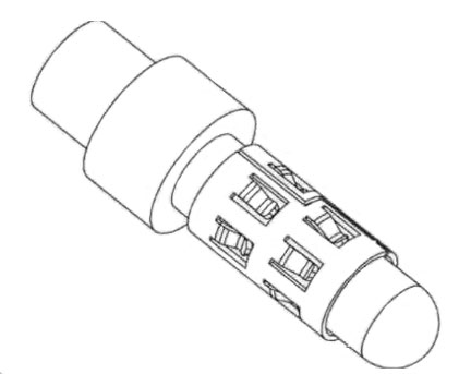

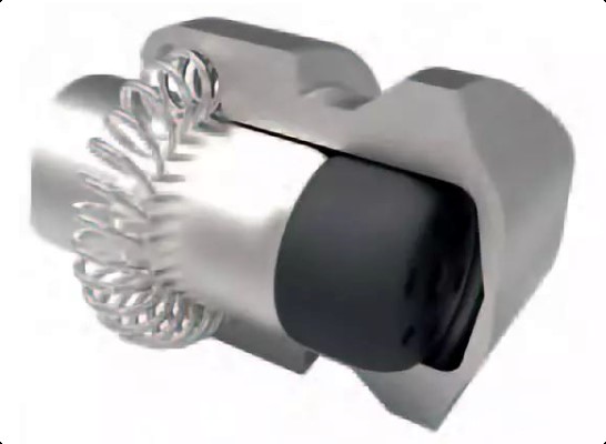
② Wire spring type contact parts
The wire spring type jack is a wire spring hole, the structure of the jack and the structure of the leaf spring type jack is similar. Only the wire spring type jack consists of multiple flexible gold-plated or silver-plated metal wires, and arranged according to the straight bus of the single-leaf rotary hyperbolic, and form a clip angle with the straight bus of the inner sleeve.
The advantages of the wire spring jack is a small contact resistance, soft plugging force and long life, anti-vibration and shock resistance, but the process is complex, the cost is also higher, the volume is relatively large, currently only applicable to round terminals.


③ Ring contact piece
The contact points between the fan leaf spring and the female terminal of the reed contact member are more than 40, fully guaranteeing the contact between the terminals.
In terms of electrical performance, the contact resistance of reed contact parts is small, the current-carrying capacity is high, the internal heat is low, and due to the characteristics of reed deformation, it can ensure high contact effectiveness under different working conditions and has good high deviation compensation; from the perspective of space and installation, reed contact parts require less internal space and are easy to assemble.
The processing process of reed contact parts is difficult and costly, and is generally applicable to round terminals.

2. High-voltage Connector Insulation / Shielding Structure Design
High-voltage wires using shielding, the same reason, high-voltage connectors also need shielding to resist interference with low-voltage electrical components, to prevent interference affecting their normal use.
Connector shielding structure according to the core can be divided into multi-core shielding and single-core shielding.
| Wire Shield - Connector Shield | <3mΩ |
|---|---|
| Connector Shield - Electrical Terminal Connector Shield | <4mΩ |
| Electrical Terminal Connector Shield - Electrical Terminal | <2mΩ |
High voltage Connector Shielding
(1) Multi-core shielding
Multi-core shielding design, the shielding of the connector is assembled from the upper and lower halves, the inner metal ring, shielding shell assembly with the outer metal ring, wire shielding network crimping. Male and female ends of the shielding shell connected by shrapnel.
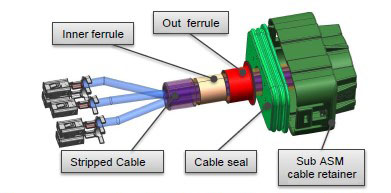

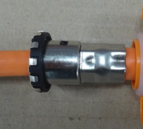
Single-core shielding is generally used shield ring crimping process, through the external force of the outer shielding flange, shielding network and cylindrical shielding shell strong bonding, and then connected to the device shell through the shrapnel, so as to achieve the purpose of electrical conductivity.

3. Anti-vibration Design of High-voltage Connectors
High-voltage connector connected to the high-voltage wires, although from the number of far less than the number of wires carried by some controllers in low-voltage electrical systems. But because of the high voltage wire diameter is thicker, relying solely on the wire pins and connectors between the jack of the fixed structure, can not fully ensure the reliability of its connection.
Especially in certain motion areas, the movement of the wire itself and the movement of the vehicle running superimposed on each other to produce vibration, will have an impact on the reliability of the connection between the pins and the connector.
Therefore, high-voltage connectors need to meet the Mechanical Vibration and Impulse Test Specification for Powertrain Components. Under the condition of carrying load, after being subjected to vibration and shock, it can still meet the electrical performance requirements, watertight performance requirements and work stably.
In order to achieve the above purpose, additional fixing is needed for the connectors connecting different high-voltage equipment to minimize the mutual movement between high-voltage conductors and connectors.
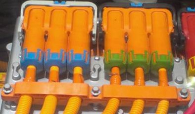
(1) Additional fixing
An additional fixing part is added at the end of the connector to fix the high-voltage conductor to the equipment housing to reduce the impact of high-voltage conductor vibration on the internal contact stability of the connector.
This design ensures the vibration resistance of the connector system and can reduce the vibration resistance requirements of the connector itself; it ensures the straightness of the conductor at the end of the connector and helps to ensure the sealing.
The use of additional fixings requires additional assembly space and has special requirements for the equipment housing.

(2) Tail locking mechanism
The tail locking mechanism is to squeeze and fix the wire through the special locking structure (tail housing) at the end of the connector. The locking structure effectively reduces the impact of wire vibration on the internal contact of the connector; it also prevents the radial crosstalk of the wire.
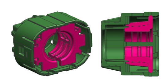

4. Anti-rotation Design of High-voltage Connectors
Round high voltage conductors will inevitably rotate under the action of torque when installed. In order to avoid additional fatigue effects on the high-voltage conductor from such rotation, an anti-rotation design is required inside the connector.
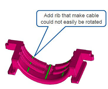
(1) Support bars clamping
Connector inner layer has a number of support bars, support bars clamping high-voltage wire bundle to prevent the wire rotation. This design has some torsional release function, but the support bars are very thin and have limited performance improvement.

(2) Polygon limitation
The use of hexagonal shields/metal sleeves/anti-rotation parts can effectively prevent the radial rotation of the wire relative to the shield.


(3) Anti-touch design
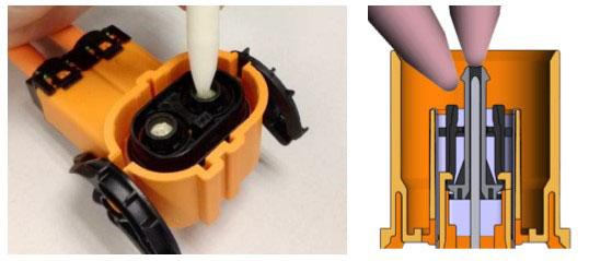
In order to prevent the danger of accidental contact between human body and live parts, the connector shell shall not have holes leading to live parts other than those necessary for operation and operation, or have corresponding anti-touch protection parts.
Referring to ISO20653 standard, the common connector anti-touch finger requirements for IP2XB.
Anti-touch mainly has two design states: in the female end using plastic structure surrounding the terminal, thus avoiding finger touching the metal terminal; in the male terminal end, the design of plastic head to avoid finger touching.

5. High voltage connector high voltage resistance performance design
Creepage distance means that when the operating voltage is too large, the transient overvoltage will cause the current to arc outward along the gap between the insulation, damaging the device or even the operator. This insulation gap is the creepage distance. The operating voltage at which the arc lasts determines the creepage distance.
In the design of high-voltage connector structure should be as large as possible to increase the creepage distance, taking into account the connector media withstand voltage of more than 4000V. After careful calculation and calibration, the connector's creepage distance is designed to more than 24mm. That can fully meet the requirements of the use of high-voltage connectors 600V.
In order to improve the connector's high-voltage performance, the connector inserted, its interface parts should fit without air gaps. Connector interface mainly includes the plug connector and socket connector plug interface, connector contacts and wire connection part. These parts need media full fill without air to reliably ensure that the connector is not struck. In order to eliminate the existence of air gaps at the interface, in the design of high-voltage connectors generally take the following measures:
- The plug interface at the use of soft insulation to ensure that the plug in place while filling the air gap.
- The insulation outside the socket contact is molded in such a way that the gap outside the contact is filled in.
- Plug and receptacle mating surface using tapered structure.
- After the connector connects the wires, part of the wire insulation extends into the connector shell insulation.
In order to improve the connector's high-voltage performance, the electric vehicle high-voltage connector selected good insulation properties, high breakdown voltage, high insulation strength, high temperature and high voltage stability, arc resistance, resistance to leakage traces, low moisture absorption of PPA (polyphthalamide) plastic.
| Conductor Cross-sectional Area | Creepage Resistor - New | Creepage Resistance - Aging |
|---|---|---|
| 2.5 | 0.17 | 0.35 |
| 4 | 0.11 | 0.22 |
| 6 | 0.09 | 0.18 |
| 16 | 0.05 | 0.1 |
| 25 | 0.035 | 0.07 |
| 35 | 0.029 | 0.059 |
| 50 | 0.025 | 0.05 |
| 70 | 0.02 | 0.03 |
Connector Creepage Resistance
6. Summary
In this paper, we introduced the main points of the design of high-voltage connector contacts, the design of connector insulation structure, the design of anti-vibration structure, the design of anti-rotation structure, the design of high-voltage resistance performance.If you are interested in our products, please contact us:[email protected]

