What is an RF Attenuator?
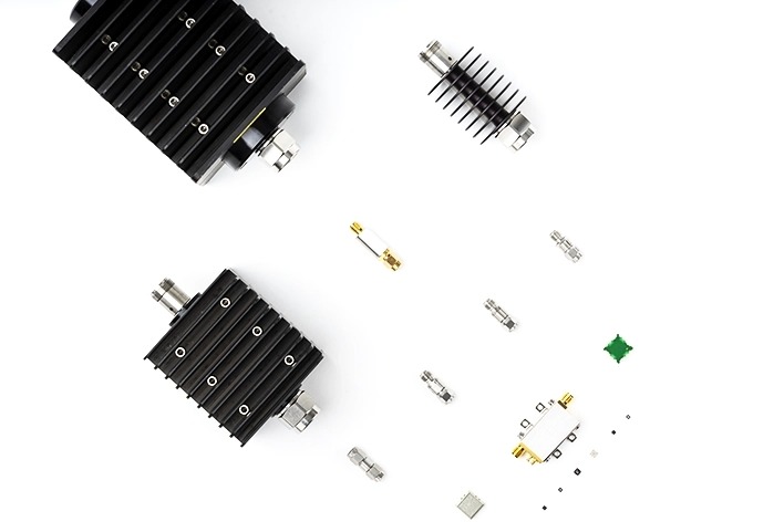
An attenuator is a control element whose primary function is to reduce the strength of the signal passing through it. Such components are commonly used to balance signal levels in a signal chain, extend the dynamic range of a system, provide impedance matching, and implement various calibration techniques in the final application design.
Types of Attenuators
From the point of view of their primary function, attenuators can be categorized into fixed attenuators with a constant level of attenuation and variable attenuators with an adjustable level of attenuation. Depending on the form of attenuation control supported by variable attenuators, they can be further classified into analog-controlled voltage variable attenuators (VVAs) and digitally-controlled digital step attenuators (DSAs).
Voltage variable attenuators allow continuous adjustment of the attenuation level and can be set to any value within a given range. Analog variable attenuators are commonly used in automatic gain control circuits, calibration corrections, and other processing functions that require smooth, precisely controlled signals.
A DSA has a discrete set of attenuation levels that adjust the signal strength in predetermined attenuation steps. Digitally controlled RF IC attenuators provide a control interface compatible with microcontrollers and are a good solution for maintaining functional integrity in complex designs.
Design Configuration
Attenuator integrated circuits can be realized in GaAs, GaN, SiC, or CMOS technology using resistors, PIN diodes, FETs, HEMTs, and CMOS transistors. Figure 1 shows the three basic topologies that serve as the basis for various attenuator design configurations: T-type, π-type, and bridged T-type networks.


Fixed-value attenuators utilize these core topologies implemented as resistors in thin-film and thick-film hybrid technologies to provide a fixed level of attenuation.
VVAs are typically available in T- or π-type configurations with diode or transistor elements that operate in a nonlinear resistive region. The desired attenuation level is adjusted by varying the control voltage using the resistive characteristics of the base element.
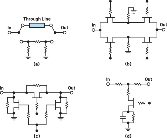
DSAs typically employ multiple cascaded cells that represent individual bits that can be switched to or from to achieve the desired attenuation level. Figure 2 shows several example configurations for DSA designs. These include configurations with integrated SPDT switches that switch input and output ports with attenuation pads and pass-through lines; switched-proportional device designs with transistors or diodes as switchable resistors; switched-resistor configurations where the resistors can be switched in-circuit or out-of-circuit; and embedded-device designs with transistors or diodes as part of the design.

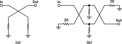
Attenuator topologies can be categorized into reflective and balanced designs, as shown in the schematic in Figure 3. Reflective devices use an equivalent attenuator connected to the output of a 3 dB quadrature coupler and typically have a large dynamic range. Balanced configurations use two 3 dB quadrature couplers to combine a pair of identical attenuators and have good VSWR and power handling.

Conclusion
There is a wide variety of integrated circuit attenuator components, certainly not limited to those discussed in this article. We can also recognize other types of integrated circuits, including frequency-dependent and phase-compensated attenuators, temperature-variable attenuators, programmable VVAs with integrated DACs, and more. In this article, however, we consider the most common classes of IC attenuators and discuss their main topologies and key specifications, which will help RF designers to select the right component for the final application.

